This example demonstrates the calculations and the steps of the volumetric well control which will help you understand about what calculations according to the volumetric procedures.

Gas kick at the bottom but unable to circulate due to drillstring plugged off. The well control information is listed below;
- Pit gain = 10 bbl
- Shut in Drill Pipe Pressure = 0 psi (drillstring plugged)
- Shut in Casing Pressure = 400 psi
- Current mud weight = 11.0 ppg
- Casing shoe depth = 6,000’MD/6,000’TVD
- Hole TD = 9,000’MD/9,000’TVD
- Hole size = 12.25”
- Casing ID = 12.5”
- Drill pipe size = 5”, 19 ppf
- BHA consists of 6.5” drill collar
- Length of BHA = 800 ft
- Average pipe per stand = 94 ft

Figure 1 – Well Information
The volumetric well control will be utilized in order to bring gas up to surface while maintaining bottom hole pressure almost constant.
Safety Factor and Pressure Increment are 100 psi.
Assumption: Gas kick at the bottom
Mud Increment
Mud Increment (MI) is calculated by the following equation

Where;
MI = Mud Increment (MI), bbl
PI = Pressure Increment (PI), psi
ACF = annular capacity factor between casing and drillstring, bbl/ft
MW = mud weight, ppg
ACF = (12.52 – 52) ÷ 1029.4 = 0.1275 bbl/ft

Mud Increment (MI) = 22.3 bbl
Volumetric Control Procedures
- We determine the Safety Factor (SF), Pressure Increment (PI) and Mud Increment (MI).
- Safety Factor (SF) = 100 psi
- Pressure Increment (PI) = 100 psi
- Mud Increment (MI) = 100 psi
- Wait for casing pressure to increase by Safety Factor (SF) + Mud Increment (MI). For this case, we will wait until casing pressure reaches 600 psi (400 + 200). At this point, the over balance is 200 psi and gas migrates up from the bottom of the well.

Figure 2 – Allow Casing To Increase by SF + PI

Figure 3 – Diagram Showing Gas Migration and Casing Pressure Increases
- Hold casing pressure constant and bleed off fluid volume by Mud Increment (MI). For this case, the volume of mud bled off is equal to 22.3 bbl. At this point, the over balance will be 100 psi.

Figure 4 – Bleed of Mud Volume by MI

Figure 5 – Diagram Showing Bleeding off Mud Volume by Mud Increment (MI) Holding Casing Pressure Constant
- Shut the well in and wait until casing pressure increases by Pressure Increment (PI). At this point, casing pressure will increase to 700 psi and the overbalance of the wellbore is 200 psi.

Figure 6 – Allow Casing Pressure to Increase by Pressure Increment (PI)

Figure 7 – Diagram Showing Gas Migration and Casing Pressure Increases
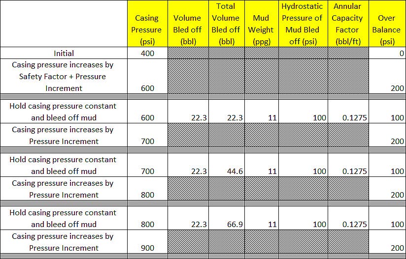
- Repeat step#3 and step#4 until gas at surface (casing pressure stops increasing) or the well kill operation can be performed with an alternative method. For example, if the pumps fails and the volumetric well control method is selected because you don’t want the bottom hole pressure increase too much. When the pumps are back in a service, other well control methods as driller’s method or wait & weight can be performed. As per this example, we will perform the volumetric well control until gas at surface.

Figure 8 – Table Demonstrates Steps of Volumetric Well Control
Referring to Figure 8, you can see that casing pressure is allowed to increase and the mud is bled off to compensate increase in bottom hole pressure. Figure 9 is a summary chart showing casing pressure and over balance during the volumetric operation. The overbalance of the well bore is maintained between 100 psi to 200 psi. In some situations when there is a chance to break formation at a casing shoe, you might consider selecting the lower figure of safety factor as 50 psi.

Figure 9 – Pressure Summary
Reference books:  Well Control Books