Oil well construction requires several casing string to reach a planned depth of a well therefore we will discuss about the basic of each casing string used in the oil wells.

In this article, we will cover the following strings;
- Conductor Casing
- Surface Casing (Structural Casing)
- Intermediate Casing
- Casing Liner
- Production Casing
- Production Tubing
The illustrations below (Figure 1 and Figure 2) are schematics of oil well in general. We will go into details of each casing/tubing based on these two images.

Figure 1 – Casing and Tubing Schematic without Liner

Figure 2 – Casing and Tubing Schematic with liner
Conductor Casing
The conductor casing is the first string run in the well and its depth range is 40 to 300 ft. In soft formation areas or offshore environment, the conductor pipe is hammered down by a large pipe hammer. In hard rock areas, driving the casing is not doable therefore a larger hole must be drilled to landing depth before running and cement this casing.
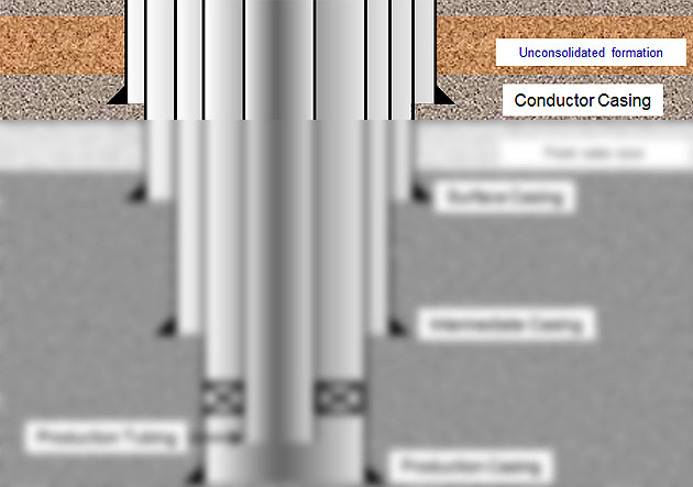
Figure 3 – Conductor Casing
Functions of conductor casing are as follows;
- Protect formation washout at the shallow depth
- Minimize loss circulation in shallow zones
- Provide a fluid conduit from the bit to the surface
- Minimize hole-caving issues. Unconsolidated formations (gravel) will fall into the well resulted in drilling issues.
Surface Casing (Structural Casing)
In some drilling areas, it may require an additional casing string between conductor casing and surface casing. This casing is called “Surface Casing (Structural Casing)” and it is typically run from 500 ft to 1,000 ft. This casing cannot be driven into the well so it requires drilling a hole before running it.
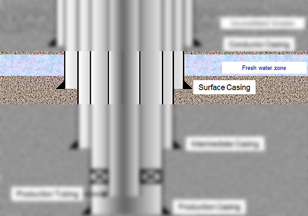
Figure 4 – Surface Casing (Structural Casing)
Functions of surface casing are as follows;
- Minimize lost circulation in a shallow depth
- Provide a fluid conduit
- Provide wellbore integrity to prevent hole-caving
- Cover weak formations when there is a well control situation
- Support blow out preventer (BOP) for well control
- Cover shallow fresh water zones from contamination
Intermediate Casing
The intermediate casing is run after surface casing and there can be several intermediate casing in one well. Drilling intermediate section most of the time requires higher mud weight than normal pressure gradient therefore the primary function of this casing is related to control high mud weight and formation pressure.
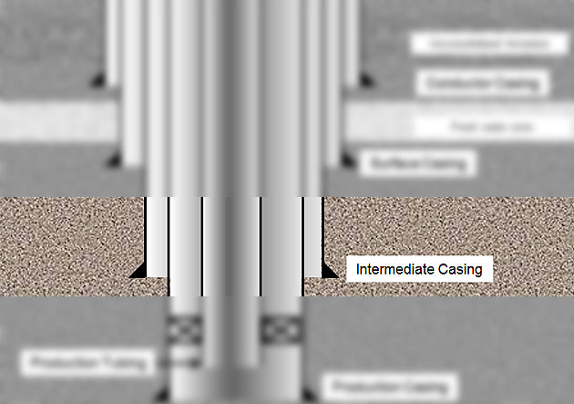
Figure 5 – Intermediate Casing
Functions of intermediate casing are listed below;
- Protect weak zones at shallower depth while drilling with higher mud weight
- Provide wellbore integrity for well control
- Isolate some formations which can cause drilling issues as lost circulations, shale sloughing, etc.
- Support weight of well control equipment
- Provide a fluid conduit
Casing Liner
Casing liner is widely used in the industry because it is a cost-effective way to run a casing string across open hole length without running all string to the surface. The casing liner can be utilized as intermediate casing or production casing. The casing liner is run into the shallower casing string and the overlap between two strings is typically around 300 – 500 ft.

Figure 6 – Casing Liner
Production Casing/Liner
This casing string/liner can be set at a depth above, midway or below the pay zone depending on completion strategies. Primary cement job is very critical for this string because it affects production from the well.
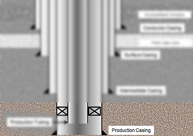
Figure 7 – Production Casing

Figure 8 – Production Liner
Functions of production casing are listed below;
- Isolate production zone(s) from other formations
- Protect completion equipment
- Provide a conduit for reservoir fluids
- Provide annular passage for gas lift injection
- Contain formation pressure in case of tubing leak
Production Tubing
The production tubing is run into the well after the production casing is in-place and all the completion equipment is run with this string downhole. The tubing must be strong enough to support production load and it should be able to workover in the future.
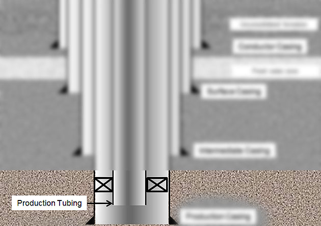
Figure 9 – Production Tubing
Functions of production tubing are listed below;
- Provide the conduit for oil, gas, water from formation(s)
- Protect the production casing from corrosion, wear and deposition from the reservoir fluids
Ref Book -> Applied Drilling Engineering Book special offer 