Quantcast
Channel: Drilling Formulas and Drilling Calculations
Viewing all 497 articles
Browse latest View live

How to Select a Scientific Calculator for Oilfield Personnel

$
0
0

Working in the oilfield, you need a scientific calculator to help you solve problems with complex formulas. As you learn from this website, drillingformulas.com, you really need a scientific calculator to help you.

How-to-Select-a-Scientific-Calculator-for-Oilfield-Personnel

There are different brand companies that design scientific calculators. However, the difference in brand names might not alter the similarity in functions and programming. When you are choosing a small scientific calculator, there are a number of factors that you should consider. These factors include; functionality and efficiency, portability and durability.

Functionality and Efficiency

The main reason why we buy a calculator is for faster computations. You should choose a calculator whose programming allows you to compute all the problems in your relevant discipline. Most of the calculators can help you in calculating normal mathematic problems, logarithms, fractions, statistics, probability, etc. If the calculator that you choose can handle the mathematics problems in your discipline, then it is a good calculator.

If you are in work sites as drilling rigs, you might not need a calculator with many technical buttons. You might just need a simple scientific calculator that will handle basic mathematic problems. There is no need of buying a very expensive calculator while you will not be using most of the functions indicated on the calculator. Instead, you can save on the purchase cost by buying a simple scientific calculator with the sine, cosine and tangent buttons among other important functions and you will still enjoy the functions of a scientific calculator.

This is the calculator (Casio Advanced Scientific Calculator with 2-Line Natural Textbook Display (FX-115ES)) that I used on the rig.

Casio Advanced Scientific Calculator FX-115ES


This calculator costs you less than 20 dollars but it will work all the hard work for you.

If you are working in the discipline that will use advanced mathematics, you really need to look into the advanced one. There is a specific scientific calculator that is programmed and designed for all math problems. The mathematics calculator is ideal for college students and engineers. It gives accurate answers with simpler decimals which enable to give more comprehensive answers. Some engineering calculators also show graphical representations. These are complex calculators that some people might not need for basic mathematics. These types of calculators are good for directional drillers, engineers (drilling, production, reservoir), geologists, etc.

The programming of the calculator determines the functions that the calculator can handle.

Texas Instruments TI-83 Plus Programmable Graphing Calculator is one of the most famous advanced scientific calculators.

Texas Instruments TI-83

Portability

Personnel especially ones working on the rig need simple scientific calculators that they can carry around easily. It is therefore important to choose a calculator that can fit in your bag or pocket. It makes it easier to hold when using and also easier to use since it has small and soft buttons. However, if you work in the office working of the complex engineering project, the advanced calculator may be suit for you.

Durability

Durability is very crucial when choosing your calculator. You need to look for a calculator that comes with a dust cover, water resistant screen and joints and buttons that are not easily unmarked after continuous use. You should choose a calculator with a clear screen too. You can ask from the store if you can use the calculator in the sun. Some screens show blurred figures when they are used outdoors.

Price should never be a determinant of the quality of calculator you want to buy. If you are guided by price you will either get a counterfeit calculator or one whose keys will fade within a couple of months making it very hard for you to use some functions on the calculator.

Find the scientific calculators at cheap price from Amazon.com.

Scientific calculators

Scientific Calculators


Advanced graphing scientific calculators

Graphing Scientific Calculators


LeNorman Ruth 87-2H Fracking Accident – Hemphill County, TX

$
0
0

I’ve got this email from my friend. The bad incident was happened in Hemphill County TX (LeNorman Ruth 87-2H Fracking Accident). I would like to share in order to raise awareness of safety in the field.

This is the detail from email that I got.

Never think your ‘Safe’ because you’ve got a good safety record; or even an excellent safety team. We sometimes tend to forget ‘what we do’ is inherently dangerous. Always think ‘at some level’ about witch way to RUN when everything goes wrong.

This was on a location where 2 wells were being worked at same time. One well a zone was being fractured, while the other well was being perforated. Hemphill county in Texas, there are two contractors involving in the operation.

They were pumping at 8,500 psig when the 7″ production casing parted, the surface casing parted above that and the Frac Head, BOP’s and all that came which landed square in the middle of the Cased Hole Truck.

Please work safe :)


LeNorman-Ruth-87-2H-Fracking-Accident-1

LeNorman-Ruth-87-2H-Fracking-Accident-2

LeNorman-Ruth-87-2H-Fracking-Accident-3

LeNorman-Ruth-87-2H-Fracking-Accident-4

LeNorman-Ruth-87-2H-Fracking-Accident-5

LeNorman-Ruth-87-2H-Fracking-Accident-6

LeNorman-Ruth-87-2H-Fracking-Accident-7

LeNorman-Ruth-87-2H-Fracking-Accident-8

LeNorman-Ruth-87-2H-Fracking-Accident-9


Drill Pipe Elongation Due to Temperature

$
0
0

Drill pipe elongation will occur because the higher bottom hole temperature.

Drill-Pipe-Elongation-Due-to-Temperature-1

Drill Pipe Elongation Due to Temperature Rule of thumbRule of Thumb

Pipe will elongate approximately 0.83 inc per 100 ft of length, per 100 degree F increase in Temperature.

We need to know the surface temperature and bottom hole temperature in order to determine pipe elongation.

The following formulas are used to determine pipe elongation.

Average Temperature = (Bottom Hole Temperature + Surface Temperature) ÷ 2

∆ Temperature = Average Temperature – Surface Temperature

Pipe Elongation = (L ÷ 100) × (∆ Temperature ÷ 100) × 0.83


Where

Average Temperature, Bottom Hole Temperature and Surface Temperature are in F.

Pipe Elongation is in inch.

L is total length in feet.

Example

Determine pipe elongation from the following information.

Total length of pipe is 10,000 ft.

Surface temperature is 80 F.

Bottom hole temperature is 375 F.

Drill-Pipe-Elongation-Due-to-Temperature-2


Average Temperature = (80 + 375) ÷ 2 = 227.5 F

∆ Temperature = 227.5 – 80 = 147.5 F

Pipe Elongation = (10,000 ÷ 100) × (147.5 ÷ 100) × 0.83 = 122.43 inch


Understand More about Pipe Rams, Variable Bore Rams and Shear Rams

$
0
0

I would like to share these 3 VDO’s demonstrating how Pipe Rams, Variable Bore Rams and Shear Rams work.

understand-more-about-rams

This eliminate confusion when the new people in the oilfield read and try to understand about these rams.

Pipe Rams – You will see that the pipe rams will work only on size of the drill string. 

Shear Rams – Both rams will be pushed against each other resulting cutting the string of the pipe.

Variable Bore Rams (VBR) - Most of the rigs prefer to use the VBR instead of the fixed pipe rams because its flexibility to work with various pipe size in the wellbore.

You can read more details about the rams preventer via this article -> Ram Preventers as Well Control Equipment

We wish you would enjoy learning this topic.


Well control quiz ebooks here -> well control http://amzn.to/WjtEvd

Reference book: Well Control Books

IADC Drilling Manual

$
0
0

IADC Drilling Manual ebook version is one of the best drilling manuals.

IADC Drilling Manual

More than 1400 pages in this ebook provide you various topics in drilling.

There are a total of 22 chapter sorted in alphabetical order from A-Z. These are the content that you can find from the IADC drilling manual.

Chapter A – Bit Classification and Grading

Chapter B – Drill String

Chapter C – Casing and Tubing

Chapter D – Drill Collars, Kellys, Subs and Heavy Weight Drill Pipe

Chapter E – Pipe Handling Equipment

Chapter F – Drawworks Brakes

Chapter G – Chains and Sprockets

Chapter H – Rotary Hose and Swivels

Chapter I – Engines

Chapter J – Pumps

Chapter K – Well Control Equipment and Procedures

Chapter L – Derricks and Masts

Chapter M – Wire Rope

Chapter N – Lubrication

Chapter O – Drilling Fluids

Chapter P – Hole Deviation and Horizontal Drilling

Chapter R – Hydraulics

Chapter T – Cementing

Chapter U – Electric Drilling Rigs

Chapter V – General Information

Chapter Y – Drilling Mud Processing

Chapter Z – Glossary

Download this ebook here -> http://bit.ly/15NpLs5

You will see the download screen like this

IADC Drilling Manual 2

Types of Drilling Rigs (Both Offshore and Onshore) – Cartoon Version

$
0
0

We would like to present some drilling knowledge in the new form. Therefore, this time we’ve created the cartoon in the topic of Types of Drilling Rigs (Both Offshore and Onshore).

Please feel free to give us any recommendation.

type-of-drilling-rig-1

type-of-drilling-rig-2

type-of-drilling-rig-3

type-of-drilling-rig-4

type-of-drilling-rig-5

Ref; http://www.wikipedia.org/

https://www.google.com

www.seadrill.com

Kick Tolerance Concept and Calculation for Well Design

$
0
0

Kick tolerance is the maximum gas volume for a given degree of underbalance which the circulation can be performed without exceeding the weakest formation in the wellbore. This article is the extended version of Kick Tolerance Calculation  which will explain more on this topic. It is very critical that drilling personnel understand its importance to well design and drilling operation.

147-Kick-Tolerance-Concept-and-Calculation-for-Well-Design-cover

There are two important factors used for determining the kick tolerance

• Kick Intensity – It is the different between the maximum anticipated formation pressure and planned mud weight. For example, the planned mud weight is 13.0 ppg and the possible kick pressure is 13.5 ppg. Therefore, the kick intensity is 0.5 ppg (13.5 – 13.0).

A zero kick intensity (swabbed kick scenario) should be used for a know area where you have less uncertainty about an overpressure zone.

 • Kick Volume – It is a gas influx entering into the wellbore from the formation. Gas kick is always used for well control calculation because it is the worst case scenario. The kick volume should be realistic figure which personal can detect the influx on the rig. In a larger hole, it allows bigger influx volume than a small hole.

Maximum Allowable Annular Surface Pressure (MAASP) and Kick Tolerance

Weakest formation point in the open hole is assumed to be at the shoe depth of the previous casing. The well bore will be fractured if a summation of hydrostatic and surface pressure exceeds the weakest pressure (Leak Off Test pressure). The maximum surface pressure before breaking the formation is called “Maximum Allowable Shut In Casing Pressure” (MASICP).

Make it simpler for your understanding. MASICP is the total of kick tolerance budget. It consists of pressure from kick intensity and hydrostatic pressure loss due to gas.

Kick Tolerance Example Calculation

Previous casing shoe (9-5/8” casing) at 6,000’ MD/ 6,000’ TVD

Predicted formation pressure at TD (10,000’MD/10,000’TVD) = 14.0 ppg

Pore pressure uncertainty = 1.0 ppg

Planned mud weight = 14.5 ppg (0.754 psi/ft)

Gas gradient = 0.1 psi/ft

LOT = 16.0 ppg

Hole size = 8-1/2”

Drill Pipe = 5”

BHA + Drill Collar = 7”

Length of BHA+Drill Collar = 400 ft

Annular capacity between open hole and BHA = 0.0226 bbl/ft

Annular capacity between open hole and 5” DP = 0.0459 bbl/ft

147 Kick Tolerance Concept and Calculation for Well Design

Calculation Steps

Maximum anticipated pressure = 14.0 + 1 = 15.0 ppg

Maximum Allowable Shut In Casing Pressure (MASICP) = (LOT – MW) x 0.052 x Shoe TVD

Maximum Allowable Shut In Casing Pressure (MASICP) = (16 – 14.5) x 0.052 x 6,000 = 468 psi

Kick Intensity = 15.0 – 14.5 = 0.5 ppg

Underbalance due to kick intensity = 0.5 x 0.052 x 10,000 = 260 psi

As you can see, when the well is in underbalance condition (260 psi), the shoe will not be broken because the MASICP is more than underbalance pressure (468 > 260).

We know that 0.5 ppg kick intensity we will have 208 psi (468 – 260 = 208 psi) before shoe broken.

It means that gas bubble can replace mud in equivalent to 208 psi before fracturing the shoe. With this relationship, we can determine height of gas kick by the following equation.

Height of gas kick = remaining pressure, psi ÷ (mud gradient, psi/ft – gas gradient, psi/ft)

Height of gas kick = 208 ÷ (0.754 – 0.1) = 318 ft.

Determine gas kick volume base on height of gas kick

We need to separate into two cases and compare the smallest volume.

1st case – Gas at the bottom

147 Kick Tolerance Concept and Calculation for Well Design 2

Volume of gas kick = Annular capacity between open hole and BHA x Height of gas kick

Volume of gas kick (bbl) = 0.0226 bbl/ft x 318 ft = 7.2 bbl


2nd case – Gas right below casing shoe

147 Kick Tolerance Concept and Calculation for Well Design 3

For this case, we need to convert gas at the shoe to the bottom condition by applying Boyle’s Laws.

Volume of gas kick = Annular capacity between open hole and 5” DP x Height of gas kick

Volume of gas kick (bbl) = 0.0459 bbl/ft x 318 ft = 14.6 bbl

Convert to the bottom hole condition

147 Kick Tolerance Concept and Calculation for Well Design 4

Volume at the bottom = (volume of gas kick at shoe x Leak off test) ÷ formation pressure

Leak off test = 0.052 x 16 x 6,000 = 4,992 psi

Formation pressure (gas kick condition) = 0.052 x 15 x 10,000 = 7,800 psi

Volume at the bottom = (14.6 x 4992) ÷ 7800 = 9.3 bbl

We can compare the kick volume from two cases like this.

1 st case : kick volume = 3.9 bbl

2nd case : kick volume = 7.2 bbl

The smallest number must be selected to represent maximum kick volume therefore kick volume is 7.2 bbl.

We wish this article could help you get more understanding about Kick Tolerance.

Ref book: Drilling Formula Book Formulas and Calculations for Drilling, Production and Workover, Second Edition

Blowout – Oilfield Disaster That You Need to See

$
0
0

These are some footage showing some oil drilling rigs were blown out and got fired. I would like to share these VDO clips to raise awareness of well control.


Oil Rig Blowout

Chesapeake Energy Nomac Rig 17 Blowout Fire

Workover Rig Blows Out Tubing

BWD Rig 136 Blowout , Rawdatain, north Kuwait

Actinia Oil Rig Blowout – shallow gas blowout

Camera captured the shallow blowout to the rig floor

Drilling rig Accident: Blowout, Rig Burns down (Ensign #59)

BBC Stephen Fry And The Great American Oil Spill

If you are interested in well control articles, please check out our link -> http://www.drillingformulas.com/category/well-control/


Learn About Drill Pipe Float Valve

$
0
0

A drill pipe float valve is a check valve installed in the drill stem that allows mud to be pumped down but prevents flow back up. There are two types of float valves which are flapper type and plunger type.

148 Drill Pipe Float Valve


The following VDO will demonstrate you the mechanism of each type of drilling float valve.

Drill Collar Weight Calculation To Prevent Drill Pipe Buckling

$
0
0

Drill collar provides weight to the bit for drilling and keep the drill string from buckling. Additionally, drill pipe should not run in compression because it can get seriously damaged therefore we need to know weight of drill collar that is enough to provide weight to the bit.


Drill-Collar-Weight-Calculation-1

Drill pipe buckle due to insufficient of drill collar

Drill-Collar-Weight-Calculation-2

Drill pipe straight because of sufficient drill collar weight

Drill collar weight in a vertical well

Drill-Collar-Weight-Calculation-3

The following formula is used to determine required drill collar weight to obtain a desired weight on bit for a vertical well.

WDC = (WOB x SF) ÷ BF

Where

WDC is drill collar weight in air, lb.

WOB is a required weight on bit, lb.

SF is a safety factor.

BF is mud buoyancy factor.

Drill collar weight in a deviated well

In a deviated well, the drill collar weight will not directly transfer to the bit because of well inclination which has direct affect on weight on bit.

Drill-Collar-Weight-Calculation-4

The following formula is used to determine required drill collar weight to obtain a desired weight on bit for a deviated well.

WDC = (WOB x SF) ÷ (BF x COS (θ))

Where

WDC is drill collar weight in air, lb.

WOB is a required weight on bit, lb.

SF is a safety factor.

BF is mud buoyancy factor.

θ  is inclination of the well.

Example: The deviated well has inclination of 30 degree in tangent section and planned mud weight is 12.0 ppg. Safety factor for this case is 25%.

What is the drill collar weight to obtain the desired WOB of 50 Klb?

Buoyancy Factor = (65.5 – 12.0) ÷ 65.5 = 0.817

SF @ 25 % = 1.25

WDC = (50,000 x 1.25) ÷ (0.817 x COS (30))

WDC = 88,333 Klb

In this case, drill collar weight in the air should be 88.3 Klb. In reality, the BHA does not only have the drill collar so you need to adapt this figure. For instant, the BHA consists of mud motor, stabilizer, LWD and HWDP which have a total weight of 30 Klb. Therefore, the actual drill collar weight is just only 58.3 Klb (88.3 – 30).

 Ref Book: Drilling Formula BookFormulas and Calculations for Drilling, Production and Workover, Second Edition

Margin of Overpull in Drillstring

$
0
0

Margin of overpull is additional tension to be applied when pulling the stuck drill string without breaking the tensile limit of the drill string. This is the difference between maximum allowable tensile load of drill string and hook load.

margin-of-Overpull-in-Drillstring

The formula for margin of overpull is described below;

Margin of Overpull = Ta – Th

Where;

Ta is the maximum allowable tensile strength, lb.

Th is the hook load (excluding top drive weight), lb.

The ratio between Ta and Th is safety factor (SF).

SF =Ta ÷ Th

Example: The drill string consists of the following equipment:

5” DP S-135, 4-1/2” IF connection, adjusted weight of 23.5 ppf = 8,000 ft

5” HWDP S-135, 4-1/2” IF connection, adjusted weight of 58 ppf = 900 ft

Mud motor and MWD, weight 20 Klb, = 100 ft

Expected hook load at TD = 270 Klb

Tensile strength of 5” DP S-135 (premium class) = 436 Klb

Tensile strength of 5” HWDP S-135 (premium class) = 1,100 Klb

90% of tensile strength is allowed to pull without permission from town.

Determine the margin of overpull from the information above.

Maximum tension will happen at the surface so 5”DP will get the most tension when pulling and since only 90% of tensile strength is allowed. The allowable tensile (Ta) is as follows;

Ta = 0.9 x 436 = 392 Klb

Th = 270 Klb at TD

Margin of over pull = 392 – 270 = 122 Klb

Safety Factor = 392 ÷ 270 = 1.45

 Ref Book: Drilling Formula BookFormulas and Calculations for Drilling, Production and Workover, Second Edition

Fishing Drill Pipe Procedure – Screw in Drill Pipe

$
0
0

Sometimes drillpipe is accidentally dropped into the well and you need to fish it out of the well. One easy option that may be feasible to perform is to use a drill string to screw into the drill pipe in the well.

 Fishing-Drill-Pipe-Procedure-screw-in

Before going into a detailed procedure, you may need to check the following conditions.

• Tight clearance between hole and tool joint

• Tool joint at the top of fish is in a good condition

Data that you need to know before going to fish the drill string

• Fish length

• Top of fish

• Weight of fish in the mud

• Actual turn to fully engage when screw in

Detailed procedure for fishing drill pipe by screwing into the fish

Fish length = xxx ft

Expected TOF = xxx ft

Weight of the fish (BHA + DP) = xx Klb


1. Trip in hole 1 stand

2. Count the actual turn of drill pipe

3. Run in hole to xxx MD (200 ft above the Top Of Fish)

4. Make up top drive

5. Break circulate with 160 GPM using current drilling fluid in the well

• Record pressure

6. Record pick up and slack off weight without rotation

7. Record pick up and slack off weight with 20 RPM

8. Record torque with 20 RPM

- In the steps 5-8, you will get the base line values when the drill string does not engage with another part.

9. Slowly run in hole without rotation

10. Tag top of fish while pumping with 160 GPM

11. Pick up 5 ft

12. Slowly run in hole with 20 RPM

13. Attempt to screw into the top of fish (tool joint)

14. Indicators if the fish is engaged.

- Increase in pumping pressure, torque, weight on bit and pick up weight.

- When picking up drill string, increment of pick up weight should close to buoyed weight of the fish (dropped drill string).

15. Flow check

16. Pull out of hole to surface.

 Note: This is the generic guideline. You may need to adapt some parameters/steps to match with your rig operation.


Mechanical Blind Back Off Drill String and Tubular

$
0
0

Mechanical blind back off is the procedure to intentionally break out stuck drill string by applying left hand torque and transmitting down hole. This is the last method to recover drill string because back-off position cannot exactly determine. One situation that I used to do the blind back of is when the perforating gun cannot be run into tubing string.

 mechanical-Blind-Back-Off-Drill-String-and-Tubular-1

Procedure to Perform Blind Back Off Operation

1. Determine drilling parameters prior to get stuck if possible.

Pick up weight __ lb

Slack off weight __ lb

Rotating weight __ lb

2. Pick up drill string at 10% over the rotating weight. Apply 50% of make-up torque with left hand turn and lock TDS. Record how many turns. Slowly work string down for 5-10 minutes to transmit surface torque to the bottom. Weight while working should be between pick-up and slack off weight.

3. Repeat step#2 with 70%, 90%, 100%, 110% make up torque

4. The string should be back off while working down.

 mechanical-Blind-Back-Off-Drill-String-and-Tubular-2

Note: The concept is to have overpull tension applied at each connection while left hand torque is transmitted into the drillstring. Once the drill string is worked, the torque will be transferred to the bottom connection of the well.


Free Promotion Download Well Control Quiz Book: Kick Detection (Warning Sign) and Shut In

$
0
0

We would like to have a free download promotion for our Kindle well control book “Kick Detection (Warning Sign) and Shut In” which is the interactive quiz book running on kindle.

3-Warning-Sign-and-Shut-in

This promotion will be only 5 days from 15-Jul-13 to 19-Jul-13.  This promotion will be end at 11:59 PM Pacific Standard Time on 19-Jul-13.

Please click this link to see the download page


http://amzn.to/OSQTxO

Once you open the page in Amazon, you will see the screen like this. You will see that the price is “$ 0.00” for this promotion period.

Click at the “Buy now with 1-Click” button“ to download the book.

 3-Warning-Sign-and-Shut-in-amazon

This Kindle book “Well Control Quiz Book: Basic Pressure In Well Control” will be automatically transferred to your kindle device / account. You don’t need to have the kindle device. You can have the tablet like as Kindle tabletsIpadSumsung Galaxy Tab, etc. This is the kindle book that I download into my Ipad.

 3-Warning-Sign-and-Shut-in-ipad

If you don’t have the kindle device, you still can download the kindle program. Read this article “How To Read the Kindle Books on Your Personal Computer” for more information.

smileyPlease leave us a good feedback if you like our book.

Riser Margin – One of Important Concepts For Deep Water Drilling

$
0
0

Riser margin in the mud weight increase below mud line to compensate bottom hole pressure in case of an accident disconnect or a failure marine riser close to the BOP stack at sea bed.

The riser margin is described by a following equation:

Riser Margin - equation

Where;

ρrm is riser margin, ppg

ρdf is drilling fluid density equivalent to formation pressure, ppg

ρsw is sea water density, ppg

L is riser length from sub sea BOP to rig floor, ft

D is true vertical depth of the well, ft

DW is water depth, ft

Note: When you consider adding the riser margin, you need to make sure that formation strength is sufficient. Additionally, you must not add trip margin and riser margin to the system because it is way over safety factor. If trip margin is higher than the riser margin, you must use the trip margin.

Example: Determine riser margin for this case.

Riser Margin

Drilling fluid weight equivalent to formation pressure = 9.2 ppg.

Sea water weight = 8.6 ppg

Length of riser to the rig = 8000 ft

Well TVD = 13,000 ft

Water depth = 8,000 ft

Riser Margin - equation 2


ρrm = 1.2 ppg

Riser margin for this case is 1.2 ppg.

Reference book: Well Control Books


Hercules Jackup Rig 265 Blows Out In Gulf Of Mexico and 44 People Evaculated

$
0
0

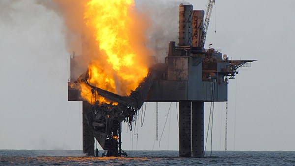
This is very bad news “ Hercules Jackup Rig 265 Blows Out In Gulf Of Mexico and 44 People Evaculated”. The details that I gather from several sources on the internet. This is the reason why well control is very important to us.

July 23rd, 2013

Forty-four workers were evacuated from a natural gas platform in the Gulf of Mexico on Tuesday after a blowout occurred, according to officials.
Crew members aboard the Hercules 265 were preparing the well for production when they hit an unexpected pocket of gas.
No injuries were reported.

Officials had said earlier that 44 workers were evacuated.

This photo released by the Bureau of Safety and Environmental Enforcement shows natural gas spewing from the Hercules 265 drilling rig in the Gulf of Mexico off the coast of Louisiana, Tuesday, July 23, 2013. No injuries were reported in the midmorning blowout and there was no fire as of Tuesday evening at the site, about 55 miles off the Louisiana coast in the Gulf of Mexico. (AP Photo/Bureau of Safety and Environmental Enforcement)
ASSOCIATED PRESS

While gas is flowing from the well, “no oil is being released,” according to the Bureau of Safety and Environmental Enforcement.
The platform, about 60 miles southwest of Grand Isle, Louisiana, is leased by Houston-based Walter Oil & Gas Corporation. The company did not respond to CNN’s requests for comment Tuesday.

A light sheen about a half-mile wide was spotted by environmental inspectors, but was “dissipating almost immediately,” the safety bureau said.
Source: CNN http://www.cnn.com/2013/07/23/us/gulf-rig-evacuation/index.html?hpt=us_c2

UPDATE: July 24th, 2013

Hercules 265 is now on fire.

The fire started about 10:50 p.m. local time yesterday.

Experts from Wild Well Control Inc. were to assess the well site overnight and develop a plan to shut down the flow of gas, said Jim Noe, executive vice president of Hercules Offshore Inc., owner of the drilling rig where the blowout occurred.

Noe stressed that gas, not oil, was flowing from the well. He said it is an important distinction because gas wells in relatively shallow areas — this one was in 154 feet (47 meters) of water — sometimes tend to clog with sand, effectively snuffing themselves out. “That is a distinct possibility at this point,” he said. “But until we have our Wild Well Control personnel on the rig, we won’t know much more.”


Tuesday’s blowout occurred near an unmanned offshore gas platform that was not currently producing natural gas, said Eileen Angelico, spokeswoman for the bureau. The workers were aboard a portable drilling rig known as a jackup rig, owned by Hercules, which was a contractor for exploration and production company Walter Oil & Gas Corp.

Walter Oil & Gas reported to the BSEE that the rig was completing a “sidetrack well” — a means of re-entering the original well bore, Angelico said.

The purpose of the sidetrack well in this instance was not immediately clear. A spokesman for the corporation didn’t have the information Tuesday night. Industry websites say sidetrack wells are sometimes drilled to remedy a problem with the existing well bore.

“It’s a way to overcome an engineering problem with the original well,” Ken Medlock, an energy expert at Rice University’s Baker Institute said. “They’re not drilled all the time, but it’s not new.”

Walter Oil & Gas Corp., the owner of the well, initially said it appeared that some of the shear rams on the rig’s blowout preventer failed to close and seal off the well. The company later said it is still investigating the incident and wouldn’t know the cause of the blowout, or why the well continues to flow, for some time.

“The crew was concerned for their safety, so once gas was detected and they felt like they did all they could do to shut in the well, they evacuated,” Mr. Noe said.


Hydrostatic Pressure Calculation Online (Metric Unit)

More News Update: Fire subsides after Hercules 265 partially collapses

$
0
0

I’ve collected several sources of Hercules 265 Blows Out. You can read the update here.


CIMB: Fire subsides after gulf rig partially collapses

A Gulf of Mexico drilling rig partially collapsed off the coast of Louisiana after catching fire because of a ruptured natural gas well, U.S. regulators said on Wednesday.

The blaze broke out after a blowout on the Hercules 265 natural gas platform at around 10:45 p.m. local time Monday.

Eileen Angelico, a spokeswoman for the Bureau of Safety and Environmental Enforcement, said no one was on board when the fire started and it was not known what sparked it. She said an investigation into the cause of incident was “well under way.”

http://usnews.nbcnews.com/_news/2013/07/24/19652537-fire-subsides-after-gulf-rig-partially-collapses?lite

Yahoo NEWS: Gulf rig partially collapses in fire off Louisiana: U.S. government.

HOUSTON (Reuters) – A shallow-water Gulf of Mexico drilling rig has partially collapsed off the coast of Louisiana after catching fire because of a ruptured natural gas well, U.S. regulators said on Wednesday.

The U.S. Bureau of Safety and Environmental Enforcement said beams supporting the derrick and rig floor on the Hercules Offshore jackup rig had crumpled over the rig structure.

A third firefighting vessel was en route to the scene, though no sheen was seen on the water’s surface during overflights conducted on Wednesday morning, the regulator said.

More details => http://news.yahoo.com/gulf-rig-fire-natural-gas-flows-ruptured-well-145808123.html

Rig Zone: Natural Gas Well Bridged; Hercules Rig Fire Continues

 The flow of natural gas has been contained at a natural gas well located in 154 feet of water 55 miles offshore of Louisiana at South Timbalier, Block 220, the Bureau of Safety and Environmental Enforcement (BSEE) said in a statement to the press July 25

More details here => http://www.rigzone.com/news/oil_gas/a/127991/Natural_Gas_Well_Bridged_Hercules_Rig_Fire_Continues

Rig Zone: Fire Out on Hercules Rig and Natural Gas Well, Gas Flow Halted

The natural gas well blowout and fire earlier in the week that spread to a jackup, causing part it to collapse, has gone out. The well owner and governmental organizations have set up a Unified Command to secure the well, the Bureau of Safety and Environmental Enforcement (BSEE) said in a release Friday.

Firefighting vessels remain on the scene, working with the well owner, the rig owner, the U.S. Coast Guard, Wild Well Control, and other relevant parties, BSEE said.

More details here => http://www.rigzone.com/news/oil_gas/a/128040/Fire_Out_on_Hercules_Rig_and_Natural_Gas_Well_Gas_Flow_Halted


Drillstring Elongation Due To a Tensile Load

$
0
0

When a tensile load is applied into a drillstring, it results in elongation of the drillstring.

Drillstring elongation due to tensile load 1

The formula to determine pipe elongation is listed below;

Oilfield unit

e = (L x T) ÷ (735,000 x W)

Where;

e = elongation, inch

L = length of drill string, ft

T = tensile load, lb

W = drill string weight, lb/ft

Metric (SI) unit

e = (L x T) ÷ (26.7 x W)

Where;

e = elongation, mm

L = length of drill string, metres

T = tensile load, kN

W = drill string weight, kg/m

Note: The equations are taken from API RP 7G 16th Edition, August 1998.

Determine the pipe elongation from the following data (this example will use “oilfield unit” for calculation.

5” DP, S-135, 4-1/2” IF Connection. The pipe specification is listed below.

Drillstring elongation due to tensile load 2

W = 23.52 ppf

Length = 8,500 ft

Pick up weight = 300 Klb

Block weight without drill string = 70 Klb

Tensile load applied into the drill string is equal to pick up weight minus block weight.

T = 300 – 70 = 230 Klb

e = (8,500 x 230,00) ÷ (735,000 x 23.52)

e = 113.1  inch

Ref books: drilling engineeringDrilling engineering books

BP’s $1Billion Battle On ‘Absurd’ Oil Rig Blast Claims As Total Bill For Disaster Hits £27.7Billion

$
0
0

BP is to appeal $1billion of compensation payments for its Gulf of Mexico oil spill, after lashing out at ‘absurd’ claims by US law firms cashing in on the disaster.

The British oil giant yesterday increased its estimate of the total bill for the 2010 disaster to an eye-watering £27.7billion.

Some £6.3billion of the total is made up of claims by people who say the accident cost them money, many of them fishermen, hoteliers and restaurant owners.

But BP is set to battle ‘fictitious’ claims by ‘greedy’ lawyers looking to use the oil company as a cash machine.

The explosion happened on 20 April 2010 triggering the worst oil spill in US history. BP says it will fight fanciful legal claims over the accident

The explosion happened on 20 April 2010 triggering the worst oil spill in US history. BP says it will fight fanciful legal claims over the accident

‘No company would agree to a settlement that pays businesses that suffered no losses,’ said chief executive Bob Dudley.

‘We want everyone to know that we are digging in and are well-prepared for the long haul on legal matters.’

Mr Dudley took the reins at BP in 2010 after an explosion ripped through its Deepwater Horizon rig in the Gulf of Mexico, killing 11 people and triggering the worst oil spill in U.S. history.

He replaced gaffe-prone predecessor Tony Hayward, who infamously enraged Americans as the disaster unfolded by declaring: ‘I’d like my life back.’

And Mr Dudley has proved a far more popular figure in the US, particularly given his roots in the Gulf Coast state of Mississippi.

Poggy fish lie dead stuck in oil in Bay Jimmy near Port Sulpher, Louisiana. Many of the claims are from businesses directl affected by the accident

Many of the claims are from businesses directly affected by the accident

But the American sought to show he was no pushover, warning that BP would take its appeal against ‘absurd’ claims all the way to the Supreme Court if necessary.


He pointed out his duty to protect the interests of investors in BP, a major component of the pension funds that will help millions of Britons through their retirement.

‘BP shareholders, of which there are many in the UK – and the dividends from this company are so important here – should be unhappy, just as they should be in the US,’ he said.

Mr Dudley added that the Gulf of Mexico compensation process was ‘curious and somewhat out of control’.

He lashed out at America’s litigation culture, saying that inflated claims against BP were a symptom of a wider problem.

He cited a claim by residents of Oklahoma against weathermen who failed to predict the devastating tornado that ripped through the US state earlier this year, killing 23 people and injuring 377 more.

And he said he was recently invited to join a £15million lawsuit against Southwest Airlines over its failure to provide free drinks coupons that it had advertised.

‘There’s something wrong with this system,’ he said.

‘The precedent is not good for America.’

Mr Dudley’s comments have been spurred by a sudden surge in claims by law firms winning compensation not just for their clients, but for themselves.

The compensation fund is administered by a judge, meaning BP has no control over who is deemed eligible for a payment.

Since BP agreed to settle, administrators of the settlement fund have paid an average £527,000 to more than 300 law firms, adding up to more than £160million in total.

But in the past week the average claim by a law firm has spiralled to nearly £1million, while one firm secured a £10million payment for itself.

The cash windfalls come on top of any fees charged to ordinary claimants such as shrimp farmers and hoteliers, who typically forfeit up to 25 per cent of their payouts to lawyers acting on their behalf.

A dam erected at Grand Isle, Louisiana, to protect the island's beaches from oil that washes ashore from the Deepwater Horizon oil rig explosion and spill in the Gulf of Mexico

A dam erected at Grand Isle, Louisiana, to protect the island’s beaches from oil that washes ashore from the Deepwater Horizon oil rig explosion and spill in the Gulf of Mexico

The rough ride given to BP contrasts with the treatment of US construction giant Halliburton, which made the cement on the British firm’s doomed well.

Halliburton has agreed to pay a fine of just $200,000 after it was found to have destroyed evidence from tests it performed on the quality of the cement used in the well.

But the financial hit is dwarfed by BP’s own costs, which it has warned could rise beyond the £27.7billion it has set aside.

BP has previously warned it faces a ‘feeding frenzy’ of lawyers, while the firm’s US head of communications last week said the firm’s efforts to meet its obligations were being exploited.

‘The Deepwater Horizon settlement could have been a model for resolving lawsuits after industrial accidents,’ said Geoff Morrell.

‘Instead it’s running into a monument to plaintiffs’ lawyers’ greed.’ 

BP intends to appeal against some £650million of payouts in total, with claims by law firms believed to make up nearly half of the total.


Source:DailyMail

Viewing all 497 articles
Browse latest View live


<script src="https://jsc.adskeeper.com/r/s/rssing.com.1596347.js" async> </script>