Quantcast
Channel: Drilling Formulas and Drilling Calculations
Viewing all 497 articles
Browse latest View live

Free Promotion Download Well Control Quiz Book: Tricky Questions and Well Control Equipment

$
0
0

We would like to have a free download promotion for our Kindle well control book “Tricky Questions and Well Control Equipment” which is the interactive quiz book running on kindle devices, Tablets, and computers.


Well Control Quiz Book -Tricky Questions and Well Control Equipment

This promotion will be only 5 days from 08-Aug-13 to 12-Aug-13.  This promotion will be end at 11:59 PM Pacific Standard Time on 19-Jul-13.

Please click this link to see the download page


http://amzn.to/16y6Zln

Once you open the page in Amazon, you will see the screen like this. You will see that the price is “$ 0.00” for this promotion period.

Click at the “Buy now with 1-Click” button“ to download the book.

 Tricky Questions and Well Control Equipment

This Kindle book “Tricky Questions and Well Control Equipment will be automatically transferred to your kindle device / account. You don’t need to have the kindle device. 

If you don’t have the kindle device, you still can download the kindle program. Read this article “How To Read the Kindle Books on Your Personal Computer” for more information.

smileyPlease leave us a good feedback if you like our book.


Pipe Light Calculation

$
0
0

Pipe light, which is a special term in a snubbing operation, describes the condition of the well which well head pressure and buoyancy acting upward again a cross sectional area of pipe is greater than weight of the string. If the light pipe condition is happened and the string is not controlled by the snubbing unit, the string will be pushed out of the well.

 Pipe Light Calculation 1

After knowing the concept of the light pipe, we will apply it to determine how many feet of tubular required snubbing into the well before the weight will overcome the surface pressure plus buoyancy force.

 Pipe Light Calculation 0

Snubbing Unit (Hydraulic Workover) works against wellbore pressure. Image from RIGZONE.COM

Basic drilling formulas for this topic

Force = Cross sectional area x Pressure

Cross sectional area = 0.7854 x Diameter2

Buoyancy factor = (65.5 – mud weight) ÷65.5

Note: The biggest size of tubular planned to run in hole is used to determine force acted to the tubular string.

For this example, we will use the oilfield unit so the

Force in lb

Cross sectional area in square inch

Diameter in inch

Mud weight in ppg

Well Information

Pipe Light Calculation 2

Surface pressure = 800 psi

Brine weight in hole = 9.0 ppg

Tubing size = 2 -7/8”, 6.4 ppf

Disregard friction for the calculation

Solution

Cross sectional area of tubing = 0.7854 x 2.8752 = 6.492 square inch

Force of wellbore pushing = 6.492 x 800 = 5,194 lb

Buoyancy factor = (65.5 – 9) ÷ 65.5 = 0.8626

Tubing must have a total weight of 5,194 lb to overcome the wellhead pressure however we need to account for buoyancy factor because this factor reduces the weight. Therefore, the total weight accounted for buoyancy factor is equal to calculated weight in the air divided by buoyancy factor.

Total tubing weight accounted for buoyancy factor = 5,194 ÷0.8626 =6,021 lb.

Total length of tubing = Total weight ÷ weight per ft

Total length of tubing = 6,021 ÷ 6.4 = 941 ft


Blowout at EOG site in Eagle Ford Shale – Nabors Rig Blows Out

$
0
0

I would like to share this NEWS.

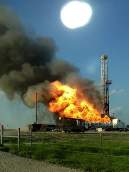
A drilling rig owned by Nabors Drilling USA blew out and caught fire Wednesday evening just before 7 pm while drilling an Eagle Ford Shale horizontal well for EOG Resources in Lavaca County, Texas.

Nabors+Rig+Fire

The well control incident occurred at Farm to Market 966 and State Highway 111 near Petersville, Texas. No injuries were reported.
Well control specialists from Houston have been called to put out the rig fire and conduct an investigation according to Shiner Volunteer Fire department Chief Mark Panus.
A nearby resident, who asked not to be identified, said her husband was in the front yard with their 4 year-old son at the time of the explosion and saw workers running. When he asked workers what happened the workers kept running so he too grabbed their son and ran, she said.

Ref: http://www.drillingahead.com/page/nabors-rig-blows-out-while-drilling-for-eog-resources-in-eagle-fo

What My Friends Think I Do – Oilfield Theme

$
0
0

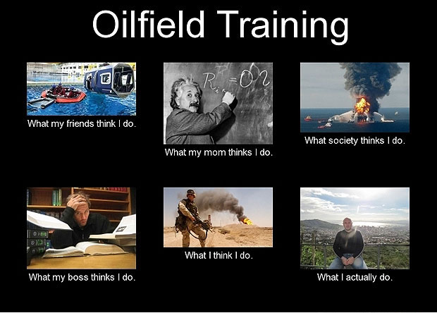
These are very funny “What My Friends Think I Do - Oilfield Theme”. You might have seen some of them before.

Oilfield Training

What My Friends Think I Do - Oilfield Training

Oil & Gas Industry

What My Friends Think I Do - oil-and-gas-industry2

Oilfield Company Man

What My Friends Think I Do - Company Man

Geology

What My Friends Think I Do - geology


Field EngineersWhat My Friends Think I Do - Field Engineer

Oil Man

What My Friends Think I Do - Oil Man

Rig Wives

What My Friends Think I Do - Rig Wives


Oil & Gas Industry

What My Friends Think I Do - Oil and Gas Industry


I wish you would enjoy this !!

Applications of Directional Drilling in Oil and Gas Industry

$
0
0

Nowadays, directional drilling is widely used around the world because it has several advantages over a normal vertical well. The applications of directional drilling are as follows:

Sidetrack Well

Applications-of-Directional-Drilling---side-track

Sidetrack is the process to drill a secondary well from an existing wellbore. Directional drilling technique is applied to successfully side track. There are advantages of sidetracking well as bypassing fish, kicking off from cement plug, extend of the producing zones, etc.

Multiple wells in one offshore location

Applications-of-Directional-Drilling---Multiple-wells-in-one-offshore-location

Multiple directional wells are usually drilled in offshore platforms. It is not economical to drill a lot of vertical wells because it would not optimize reservoir target in comparison to directional wells. Some offshore platforms can have several wells. With this development technique, it greatly improves the economics of field development.

Control Vertical Wells

Applications-of-Directional-Drilling---Control-Vertical-Wells

It is not simple to drill a vertical hole because a vertical BHA sometimes tends to created crooked well path. Without the directional BHA, it is very difficult to bring the well back into a vertical path after it deviates from the original plan. The simple way to drill a good vertical well is to have a directional BHA so when the well does

Horizontal Wells

Applications-of-Directional-Drilling---Horizontal-Wells

One of the advanced directional drilling methods is horizontal drill. The horizontal well typically has inclination at least 80 degree. Since the horizontal well exposes to a lot of drainage areas, only one well can produce a lot of hydrocarbon.

Relief Wells

Relief wells are special directional wells planned to drill to hit the blow out well. When the blowout well is drilled into, a special well control procedure will be conducted to control the blowout well. There are several examples as in Macondo well (blow out incident on 20 April 2010).

Application-of-Directional-Drilling---relief-well

Application-of-Directional-Drilling---relief-well-2

A BP graphic shows how relief wells have been drilled to intercept the Macondo well that had been leaking millions of gallons of oil and gas into the Gulf of Mexico.


Overcome Geological Structure

Applications-of-Directional-Drilling---Salt-Dome

One of problematic issues of drilling is to drill into a salt dome. In order to eliminate this issue, the well is directionally drilled around and underneath the salt dome.

Reach Inaccessible Locations


Some areas where the rigs cannot be placed are in accessible as town, mountain. The directional wells are drilled to the producing zones underneath these areas.Applications-of-Directional-Drilling---Reach-Inaccessible-Locations


Another Bad Oilfield Incident – Drill collar in drillers shack

$
0
0

I don’t really know much about the detail of this incident. If you know, please feel free to share with us so other people will learn from this event.

Drill Collar laid across the rig floor

Drill collar in drillers shack001

Drill shack was totally damaged.

Drill collar in drillers shack002

I hope the driller did not get hurt.

Drill collar in drillers shack003

The drill collar was dropped inside the driller shack.

Drill collar in drillers shack002

This was another view which was pretty scary.

Drill collar in drillers shack005

The broken glass was everywhere.

Drill collar in drillers shack006

The panel and joy stick were damaged.

Drill collar in drillers shack007

The drill collar was dropped into the shack.

Drill collar in drillers shack008

Everything in the room was ruin.

Drill collar in drillers shack009

Look at the derrick. Two drill collars laid across the derrick.

Drill collar in drillers shack010

The drill collar, bit, wear bushing, etc on the rig floor.

Drill collar in drillers shack011

Few more pictures are below.

Drill collar in drillers shack012

Drill collar in drillers shack013

Drill collar in drillers shack015


International Association of Drilling Contractors (IADC) Well Control Kill Sheet

$
0
0

International Association of Drilling Contractors (IADC ) is one of important organizations in drilling industries.

well-control-killsheet

One of their main contributions is well control. IADC has the well control courses and material that are very useful to all people in the drilling industry. Besides IWCF, IADC also distributes their kill sheets to everyone and you can find the download links down below.

Wait and Weight well control

Wait and Weight  Surface Stack

Wait and Weight Method – Field units (US Customary)

surface-Wait and Weight Method - Field units (US Customary)


Wait and Weight Method – Metric units

surface-Wait and Weight Method - Field units (US Customary) surface-Wait and Weight Method - Metric units


Wait and Weight Method – SI units

surface-Wait and Weight Method - SI units

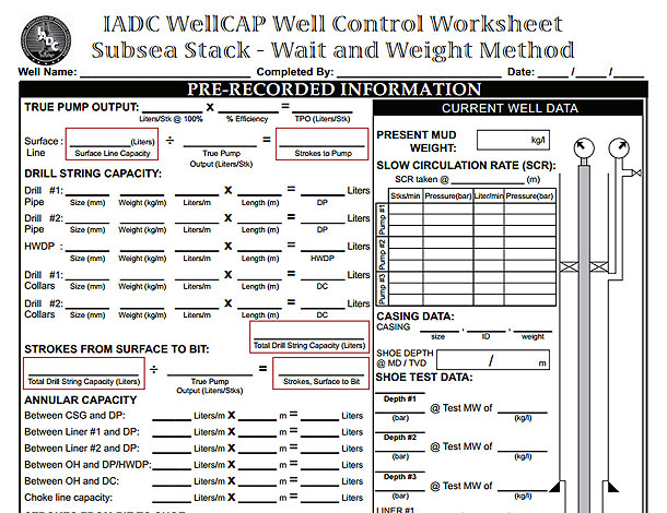
Wait and Weight Subsea Stack Version

Subsea Stack Wait and Weight Method – Field units (US Customary)

sub-sea-Wait-and-Weight-Method---Field-units-(US-Customary)


 Subsea Stack Wait and Weight Method – Metric units

Subsea-Stack-Wait-and-Weight-Method---Metric-units

Subsea Stack Wait and Weight Method – SI units

Subsea-Stack-Wait-and-Weight-Method---SI-units

IADC – Kill sheet for bullheading


Bullheading draft killsheet, Field units (US Customary)

Bullheading-draft-killsheet,-Field-units-(US-Customary)

Bullheading draft killsheet, Metric system

Bullheading-draft-killsheet-Metric-system

Bullheading draft killsheet, SI units
Bullheading-draft-killsheet-Metric-system Bullheading-draft-killsheet-SI-units


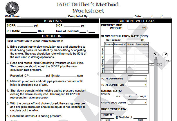
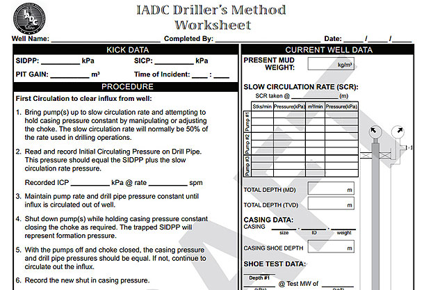
 Driller’s Method well control - Draft version

Driller’s Method – Field units (US Customary)

Driller’s-Method---Field-units-(US-Customary)

Driller’s Method – Metric units

Driller’s-Method-–-Metric-units


Driller’s Method – SI units

Driller’s-Method---SI-units


What Threatens the Future of the Oil and Gas Industry?

$
0
0

In the future the oil and gas industry faces numerous challenges. There’s have been some large spills and more environmental concerns in the oil and gas industry recently such as the large BP oil spill in the Gulf of Mexico and other concerns about how we deal with oil and gas in our environment. There are several things that threaten the future of these industries.

future-of-oil-gas-industry

Fracking

Fracking or hydraulic fracturing is raising concerns about earthquakes and the use of water. The fracking industry is trying to address concerns about this practice but it’s unclear if this will be enough. There are many groups that have big concerns about this practice and its impact on our environment. Fracking could be a big game changer in the oil and gas industry but the concerns over this practice might be enough to shut down the practice. The industry needs to ensure that they address the concerns about fracking or they could face a sever backlash in coming years that they may not be able to recover from.

Global Market Volatility

The volatility of the market could impact the amount of oil and gas that’s produced in the world. The economic conditions, wars, and so on have a huge impact on the oil and gas industry as many of the richest counties in oil and gas have economic as well as government instability issues. The instability of the entire world impacts the oil and gas industry going into the future.

Large Accidents

The BP oil spill still hangs over the entire oil and gas industry because it paints a bad picture on the entire industry. The fact that any spill, large or small impacts the environment makes it difficult for the oil and gas industry to move into the future. There needs to be stricter regulations and safety precautions taken in this industry. If there are more large spills that grab the world’s attention the entire industry will be under huge pressure to make sweeping changes. People aren’t going to tolerate any more large oil and gas disasters because we have an increased concerns about our fragile environment. Companies will need to focus closely on their operations to ensure they aren’t creating conditions that result in large spills.

10 Main Concerns in Oil and Gas Industry

Here are 10 main concerns going into the future for the oil and gas industry that must be addressed.

• Regulatory and legislative changes which increase cost of compliance or oil and gas companies making it harder to operate

• The volatile cost of oil and gas on the market and the demand for these products

• The need to find new reserves and to expand existing reserves

• The hazards of working o the job such as oil well blowouts, spills and injury or death to personnel

• Natural disasters which shut down operations or make it difficult to get oil and gas out to consumers. The fact that wells or rigs could be destroyed

• Inaccurate estimations of oil reserves which requires more oil to be produced

• Not enough capital to acquire oil and gas or debts to oil producing companies which can’t be paid

• Regulations, health concerns, and impacts on the overall environment from oil and gas drilling and other practices causing backlash against these companies due to increased environmental awareness and understanding

• General concerns about the economy and stability of countries producing oil and gas

• Competition in the industry from energy alternatives

These are some of the concerns the oil and gas industry will need to look at going into the future. Oil and gas should be with us for a long time to come but the entire industry needs to ensure they do the right thing moving forward and address concerns people have with the entire industry.


Lubricate and Bleed in Well Control

$
0
0

In some special well control cases, you will not be able to circulate kick out of the well then the kick is brought up to the surface using special well control procedure like “Volume Metric Method”. At this point, surface pressure is the height because of decreased hydrostatic pressure in the well bore.

150-Lubricate-and-Bleed

How can we remove the gas out of the well bore without allowing more influx coming into the well bore for this scenario?

This is the time that we must perform a special well control procedure called “Lubricate and Bleed”. Lubricate and bleed procedure is the way to remove the gas when the circulation is impossible to conduct. The basic theory is the same as Volumetric Well Control Method but it is just a reverse process. Surface pressure will be replaced with hydrostatic pressure by pumping drilling fluid into the wellbore. The gas and drilling mud are allowed to swap the places and amount of surface pressure will be bled off later.

If you use the current mud weight to perform the lubricate and bleed procedure, the well will not be killed and there is remaining surface casing pressure. Only surface casing pressure will be decreased to where it balances to formation pressure. In many cases, it is sometimes desirable to pump heavier mud in to the wellbore and hopefully it will kill the well too.

You will wonder why I use the phase “hopefully kill the well”. The reason is you may not have enough hydrostatic height to create extra hydrostatic head to just balance the formation pressure. This is based on case by case.

The lubricate and bleed procedure is listed in the following steps:

Step 1 – Determine hydrostatic pressure

Determine hydrostatic pressure of 1 bbl (I use the oil field unit) of mud that will be pumped into the well.

Step 2 – Lubricate

Slowly pump a desired volume into the well. The amount of volume depends on well conditions and it may change during the process. Increasing in surface pressure can be estimated by utilizing Boyle’s Laws (P1V1 = P1V2) and every one bbl of mud pumped into the well, the gas size is reduced by one bbl.

During lubricating, surface casing pressure will be definitely increase. The amount of pressure increase will depend on the volume of gas being compressed. Small pressure increase indicates large volume of gas. Additionally, Maximum Allowable Surface Casing Pressure (MAASCP) will reduce because the increase in hydrostatic pressure during lubrication. Since gas volume also decreases every time that gas is bled off, you may reach the point to stop lubricating operation in order to prevent breaking out the wellbore. At this point you will have gas in the wellbore but the lubricate and bleed procedure cannot be performed any more. In order to know this figure, you may need to play with the kill sheet to find this stopping point. By adjusting parameters in the kill sheet, you can minimize this issue.

Step 3 – Wait

Wait for awhile to allow gas and mud swapping out. Drilling mud properties as mud weight and rheology affects on this step. You need to be patient.

Step 4 – Bleed off pressure

Bleeding gas from the surface until the amount of pressure is equal to hydrostatic pressure of mud pumped in hole. If you know that you lubricate in 50 psi, only 50 psi of gas must be bled off. It is very important to bleed only gas. During this process if you see mud on surface, you must stop and allow gas to swap out. For instant, you plan to bleed a total of 50 psi but you observe mud coming out when you bleed only 30 psi, you stop the bleeding process and shut the well in. Then, you continue bleeding the remaining 20 psi later.

If the mud is accidentally allowed to come out during this bleeding process, the bottom hole pressure will reduce resulting in more influx coming into the wellbore.

Step 5 – Repeat step 2 to 4

Repeat step 2 – 4 until you get the gas out of the well or the desired surface casing pressure is reached. As you know, you may not be able to kill the well with this method because total hydrostatic head is not sufficient to balance the wellbore.

  Well control quiz ebooks here =>well control http://amzn.to/WjtEvd

5 Factors that Affect Crude Oil Prices

$
0
0

Crude oil prices are impacted by supply and demand in the marketplace. There are many things that cause supply and demand to go up or down. Here are the main factors that impact crude oil prices.

Factors-that-Affect-Crude-Oil-Prices

Basic Demand

Oil will go up in price if there’s some factor that impacts the price. This could be global instability, a disruption in supply due to disasters, and so on. If there’s less of a demand for crude oil due to oversupply in the marketplace, the demand for crude oil will go down.

Oil and the Market

Oil is a commodity and it’s one of the most in demand products. We really can’t do anything economically without oil because we need it for transportation as well as in the production of many of the products we use each day. Crude oil is impacted in price by what the markets do and if there’s volatility in the markets oil will usually be impacted by this. In the summer for example, oil usually goes up in price because more people are traveling and there’s a higher demand for oil. The crude oil helps to determine the price of gasoline that we use in our vehicles. The price of crude oil impacts the price of the gasoline at the pump because use the oil to produce gas. The crude oil may make up as much as half the price of a gallon of gasoline.

Crude oil prices can fluctuate all year long because of the supply and the demand for gasoline. If gas is in high demand then crude oil prices will go up. If there’s less demand for gasoline then the price of the crude oil will go down. Crude oil prices are directly tied to the cost of gasoline in the market.

Costs

The production, distribution, transmission, and the price of the actual crud oil all factor into the costs of crude oil and the fluctuation of prices. If there’s a major refinery fire for example, and that refinery goes offline, the price of crude oil may go up for a short time if that refinery is a major producer. Once crude oil is refined and distributed the retailer that sells the gas or other oil products will set the price for those products and this is largely determine by the market. The retailer must be able to cover their own costs. At the pump many gas stations will compete with prices to get your business. If there’s a problem in the crude oil supply chain this is reflected at the pump when you go to buy your gasoline.

Regulations

The cost of crude oil can be impacted by government regulations that are in place to clean up the air. There’s a need for cleaner burning gasoline and many states must meet these regulations. Which can impact crude oil prices. Different regions need specific formulations of gasoline which can drive up the costs of producing that fuel to meet the regulations for that fuel in one specific area. Taxes can also play a role in the price of crude oil too. Permits for building in the US are stagnant and no new refineries have been built since the 1970s. This means the US imports its gasoline which further drives up prices of crude oil.

Disasters/ World Problems

Anything that disrupts the crude oil supply chain can impact prices. For example, a hurricane in the Gulf of Mexico may wipe out the production capability of several oil rigs for several weeks or even months. This can impact the prices of crude oil. A lot of oil comes from the Middle East and instability yin an oil producing country can cause the prices to fluctuate. If the crisis in a country is severe then the markets price of crude oil crude skyrocket if it’s deemed that the supply is going to be interrupted because of the crisis.

Crude oil fluctuates in price all the time. There’s no telling what is going to drive the price up or bring it back down. The volatility in the price of crude oil is something we just have to live with.


The Bit – Rotary Drilling Book Review

$
0
0

There are not many books about drilling bits in the market. Today, I would like to share with you about this book, “The Bit” which is a very good book in the rotary drilling series.

 The Bit Rotary Drilling 1


The book is written in a simple language therefore everyone can understand this topic so easy.

 The Bit Rotary Drilling 2

Let’s take a look what you will learn in this book.

Formation and bit design – Learn about rock properties affecting how the bits are designed. Learn the process of how to select the right bit for the job.


Roller cone bits

The Bit Rotary Drilling 3

Basic about the roller cone bits and components. Types of roller cone bits and how to manufacture them. Operational concern when the bits are used. Types and characters of cutters used for the bit.

Types of cutter and bit wears that may happen. You will understand cause of failure and how to prevent it.

 The Bit Rotary Drilling 4

Bit hydraulics – learn about drilling fluids and hydraulic effecting on bits. Different jet nozzles and their applications.


Diamond Bits

The-Bit-Rotary-Drilling-5

This section you will learn about the diamond bits. There are several interesting topics

• Application of the diamond bits and why we need to use this bit

• Type of diamond used

• Shape and profile affecting drilling application

• Diamond bit plots and setting

• Chanel design


Polycrystalline Diamond Compact (PDC) Bits

 The Bit Rotary Drilling 6

PDC bits are widely used in drilling industry nowadays and this book will explain you several aspect of the PDC. The following topics are in this book


• PDC applications

• PDC profiles – short parabolic, shallow cone, parabolic

• PDC cutter angle – back rake angle and side rage angle

• Bit wears – delemination, long substrate bond failure, spalling and abrasion

• Whirl affects the bit life


Special-Purpose Bits

The Bit Rotary Drilling 7

This section is about special-purpose bits that are built for special jobs. The following topics in this section are as follows;

• Air bits

• Two-cone bits

• Jet deflection bits

• Anti-whirl bits

• Ecentric bits

• Core bits

• Side track bits


Bit Selection – This section will talk about how to select the proper bits (roller cone and diamond) that are suitable for formations. This is very excellent section that helps people get the right bit without a lot of trial and error.

Bit Performance – This chapter describes about drilling parameters (WOB, rotary speed, etc) affecting on drilling performance.

Dull Bit Grading – The industrial standard for dull bit grading with example.

The Bit Rotary Drilling 8

Conclusion – If you are interested in drilling bits, this book is excellent for you. All about the drilling bits are in this book and the contents are written in simple oilfield language. You don’t need to be an engineer to understand the content. Please check out the link to buy this book from Amazon.com => The-Bit-Rotary-Drilling-1http://goo.gl/wa4LoU


Understand Pressure Loss (Frictional Pressure) in Drilling System

$
0
0

Frictional pressure is pressure loss acting in the opposite direction of fluid flow and today we will look into each component in pressure therefore you will get clearer picture about the frictional pressure in drilling system.

Let take a look at the simple diagram below.

Understand Frictional Pressure in Drilling 1

A mud pump creates power to move drilling fluid from point A to C and the frictional pressure or pressure loss is the amount of pressure required to transfer fluid.

Pump pressure is 2,000 psi at the starting point (“A”) and at the end point (“C”), pressure is 0 psi. This tells you that you need 2,000 psi to overcome the frictional pressure in order to move the fluid from point “A” to point “C”.

“Differential pressure between two points in the system is pressure loss while fluid is moved from one to another point.”

What is the pressure loss from “A” and “B”?

At point “B”, the pressure remaining is 1,000 psi, therefore pressure loss between “A” and “B” equals to 900 psi (2,000 – 1,100).

What is the pressure loss from “B” and “C”?

At point “C”, at an atmospheric condition, the pressure is 0 psi, therefore pressure loss between “B” and “C” equals to 1,100 psi (1,100 – 0).

Apply This Concept Into Drilling

Then we will apply this concept to understand about pressure loss in the drilling system. The simple drawing below demonstrates a simple circulating route of drilling fluid while drilling.

Understand Frictional Pressure in Drilling 2


Analysis of Pressure Loss in The Drilling System

We need to analyze each section to understand each pressure loss component.

Understand Frictional Pressure in Drilling 3

 Surface -> ∆ PSI Surface Equipment

Inside drill string, drill collar, BHA -> ∆ PSI Drill Pipe + ∆ PSI Drill Collar and BHA

Bit -> ∆ PSI Drill Bit

Annulus -> ∆ PSI Annulus DC and BHA / OH + ∆ PSI Annulus DP/OH + ∆ PSI Annulus DP/CSG

Where;

∆ PSI Surface Equipment = Pressure loss in surface equipment

∆ PSI Drill Pipe = Pressure loss in drill pipe

∆ PSI Drill Collar and BHA = Pressure loss in drillcollar and BHA

∆ PSI Drill Bit = Pressure loss across the bit

∆ PSI Annulus DC and BHA / OH = Pressure loss in the annulus between DC/BHA and open hole

∆ PSI Annulus DP/OH = Pressure loss in the annulus between drill pipe and open hole

∆ PSI Annulus DP/CSG = Pressure loss in the annulus between drill pipe and casing

In order to pump drilling fluid from the mud pit and back to surface, pump pressure equals to summation of pressure loss of all equipment which can be described in the following relationship.

Pump pressure = ∆ PSI Surface Equipment + ∆ PSI Drill Pipe + ∆ PSI Drill Collar and BHA + ∆ PSI Drill Bit ∆ PSI Annulus DC and BHA / OH + ∆ PSI Annulus DP/OH + ∆ PSI Annulus DP/CSG

Example: Well depth is 12,000’MD/10,000 TVD and planned pump rate is 400 GPM. Based on drilling hydraulics calculation, the pressure loss component s are listed below;

∆ PSI Surface Equipment =50 psi

∆ PSI Drill Pipe = 500 psi

∆ PSI Drill Collar and BHA = 30 psi

∆ PSI Drill Bit = 1500 psi

∆ PSI Annulus DC and BHA / OH = 200 psi

∆ PSI Annulus DP/OH = 600 psi

∆ PSI Annulus DP/CSG = 450 psi

What is the pump pressure required to circulate at drilling rate?

Pump pressure = total pressure loss of all equipment together.

Pump pressure = 50 + 500 + 30 + 1500 + 200 + 600 + 450 = 3,300 psi.

I wish this explanation and exercise would help you get more understanding about pressure loss.

 Note: Additional drilling formulas for hydraulic calculations that you might need to know.

Reference:  Drilling Hydraulic Books

What are differences between Full Opening Safety Valve (TIW valve) and Inside BOP valve (Gray Valve)?

$
0
0

Two types of stabbing valves that must be prepared for well control are Full Opening Safety Valve (TIW valve) and Inside BOP valve (Gray Valve). We would like to describe what the differences between two valves are.

What-are-differences-between-TIW-valve-and-Grey-Valve-3

Full Opening Safety Valve or TIW valve

Full Opening Safety Valve or TIW valve is a ball valve designed for high pressure condition and it can hold pressure from both directions. It is called “Full Opening” because when the ball valve is opened; the flow path through the valve has a smooth inside diameter. One thing that you need to remember is that the term “Full Opening” does not mean that the ID of the valve is the same of drill pipe ID.

 What are differences between TIW valve and Grey Valve 1

 Figure 1 Full Opening Safety Valve

The valve should be always located on the rig floor and left in the open position. Additionally, you need to ensure that personnel on the rig have a right wrench to close the valve. The valve left in the open position is critical because the valve can be stab into drill string if the well flows through drill pipe.

For good drilling practices, you must have all size full opening safety valves which can be screwed into each size of drill pipe, drill collar, tubing, etc on the rig. When there is any string in the hole, the correct connection of the valve must be ready on the rig floor to stab in. Furthermore, it is a good practice to install the valve when there is a sting left on the rotary table during rig performs any tasks. The full opening safety valve should be used for shutting the well in while tripping.

 Inside BOP valve (Gray Valve)

Insider blowout preventer (IBOP) valves have several industrial names as drill pipe float valves, Gray valves, Omsco valves and drop-in dart valves.

What are differences between TIW valve and Grey Valve 2


Figure 2 Inside BOP (Dart Type)

 This valve is a non-return valve (check valve) allowing pumping through the valve into the drillstring but it prevents upward flow and the more widely used type is “dart-type”. The dart is used to hold the tool open therefore it is possible to stab the valve while the fluid is flowing through the drillpipe. With the IBOP valve installed in the drill string, it allows you to strip in hole without mud flowing through the drillsting. The IBOP valve should not be used for shut the well in while tripping.

Reference book: Well Control Books

Basic Understanding about Drill Pipe

$
0
0

Drillpipe is seamless steel pipe made up in the drill string and it is the major component of the entire drillstring. Typically, 90% – 95% of the total length is drill pipe. Thread connection of drill pipe is called “Tool Joint”. One end of drill pipe has a female end which is named as “Box” (see Figure 1).

basic-Understanding-About-Drill-Pipe-1-Box-Connection

Figure 1 - Box End of Tool Joint

Another end of drill pipe is a male end known as “Pin” (see Figure 2).

 basic-Understanding-About-Drill-Pipe-2-Pin-Connection

Figure 2 - Pin End of Tool Joint

Component of Tool Joints – Pin (Figure 3)

 basic-Understanding-About-Drill-Pipe--Figure3

 Figure 3 - Pin End Component

Component of Tool Joints – Box (Figure 4)

basic-Understanding-About-Drill-Pipe--Figure4

Figure 4 - Box End Component

Figure 5 shows when the drill pipes are made up together.

basic-Understanding-About-Drill-Pipe--Figure5

Figure 5 - Drillpipe Make Up

 Each joint of drill pipe is sometimes called “Single” and the length of each single is classified based on three API length range in the table below (see Table 1).

 basic-Understanding-About-Drill-Pipe-3

Table 1 - API Range of DrillPipe

The most common drill pipe length is commonly in “Range 2 (R2)”. Each joint of drill pipe does not have the same length therefore all drill pipes must be measured to get an exact length. Drilling depth is measured by length of drill string (drill pipe, drill collar, BHA) hence the right measurement is the key of the right depth.

The drill pipes are manufactured in various sizes, material, etc. In order to standard pipe grade, API classifies drill pipe into several classes based on the table below (Table 2).

basic-Understanding-About-Drill-Pipe-4

 Table 2 - API Drill Pipe Grade

In the industry, there are several drill pipes manufactured from several companies. Therefore, in order to get the detailed specification of particular pipe, it is recommended that you need to find data from the manufacture spec sheet.

basic-Understanding-About-Drill-Pipe-5

Figure 6 - 4.000″ WEAR KNOT 14.00ppf 0.330″ wall IU

 We wish you would enjoy learning from our article. Please feel free to leave us some comments.


Texas-Drilling Rig Hits Gas Pipeline Then Explodes

$
0
0

November 14th, 2013 MILFORD, Texas -Hundreds of people in Ellis County were evacuated and others were asked to stay away from the area where a gas pipeline caught fire Thursday morning.

It happened at about 9:30 a.m. November 14th, 2013 near the intersection of Highway 77 and FM 308 in Milford.

Ellis County spokesman James Saulter said a Chevron crew had been conducting a type of drilling when the explosion happened.

Video from SKY4 showed heavy flames rising from what appeared to a rig in a rural field. It was surrounded by several charred work trucks. The large plum of black smoke was visible from Interstate 35E.

No one was hurt and there were no reports of damage to any nearby homes or businesses, Saulter said.

However, officials are still concerned about the fire spreading to other pipelines in the area.

The whole city of Milford, which has a population of about 800, was evacuated. Students were moved to schools in the nearby town of Italy.

Traffic on FM 308 was rerouted between Highways 22 and 77. Motorists in the area were asked to use I-35E as an alternative to Hwy. 77.

Chevron will let the pipeline burn itself out, which is expect to take about 24 hours, Saulter said.

 More Photos

Ref: http://www.myfoxdfw.com/story/23969008/gas-pipeline-explodes-in-ellis-county#ixzz2kfzCxDPt


North America and Canada Oil and Gas Job Opportunities Boom

$
0
0

With the development of industries such as shale rock, tar sands, and deep water drilling in the United States and Canada, the oil and gas industry in North America has been booming. It is predicted that the U.S. oil production could outpace Saudi Arabia and that North America could become an exporter of energy across the globe. Since this industry is still being developed there are countless open positions from construction to the production of oil and gas itself.

Historically the United States has always had a shortage of labor. The country’s economic output is always greater than its ability to recruit the skilled labor that is needed to keep up with demand for US goods and services. This is why the United States has always required immigration to provide the labor. Most Americans have a negative birth rate, and without young people, industry cannot keep up.

This is why the oil and gas industry is paying handsomely to those people who wish to get into this sector. There simply aren’t enough people to go around in order to get the job done. The energy sector is short on almost every form of skilled and unskilled position. They need truck drivers, equipment operators, and construction workers. They need accountants, geologists, project managers, etc. The problem is that they can’t recruit skilled help fast enough.

If you are considering a career change, now might be a real good time to enter into the oil and gas industry. Here are a few pointers that will help you make this change a success. First of all, you should consider moving to a place that is producing oil. Now this can be a little scary because you would have to leave your job and home and then move a strange area such as the Dakotas with the hope that you might find a job. However, this does show the companies that you are committed and they are more inclined to hire you if they don’t have to worry about relocation.

You need to be prepared to take entry-level positions. There is plenty of opportunity for advancement later, but if you aren’t willing to start at the bottom and work up, then you are disqualifying yourself for the better paying jobs down the road. Nobody is going to put you in charge of expensive equipment or a project until they know that you can be trusted to do the job correctly. Oil and gas production is highly specialized and is hazardous. You need to understand what you are doing first before moving up.

Lastly, be prepared to work for smaller contractors and get dirty. Most oil companies sub-contract out work to smaller businesses. It’s usually easier to get your foot in the door in the smaller contractors. Also bear in mind that oil production is dirty. You need to be willing to work around smells, fires, tar, and dirt. It’s just simply part of the gig!

 Great Ebook for Oilfield Jobs

oilfield-resume-ebookOilfield Resume

square-oilfield-interview-sSuccessful Oilfield Interviews

Basic Understanding About Positive Displacement Mud Pumps in Drilling Industry

$
0
0

Positive displacements pumps are generally used on drilling rigs to pump high pressure and high volume of drilling fluids throughout a drilling system. There are several reasons why the positive displacement mud pumps are used on the rigs.

• The pumps can work with fluids with high solid content.

• There are wide ranges for pressure and flow rate.

• They are more reliable and able to pump at tough conditions.

• They are easy to operate and maintain.

Duplex and Triplex pumps are positive displacement pumps which are commonly used in the oilfield.

Duplex pumps – 2 cylinders, double acting

 positive Displacement Mud Pumps in Drilling Industry 1

Figure 1 Duplex Pump

The duplex pumps have two cylinders with double acting. It means that pistons move back and take in drilling mud through open intake valve and other sides of the same pistons, the pistons push mud out through the discharge valves.

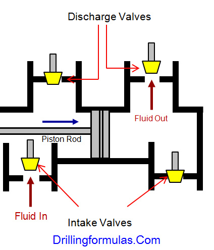
The following diagrams demonstrate how the duplex mud pumps work.

positive Displacement Mud Pumps in Drilling Industry 2

Figure 2 Position of Piston Rod and Fluid Movement of Duplex Pump

When the piston rod is moved forward, one of intake valves is lift to allow fluid to come in and one of the discharge valve is pushed up therefore the drilling mud is pumped out of the pump.

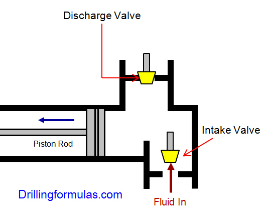
 positive Displacement Mud Pumps in Drilling Industry 3

 Figure 3 Position of Piston Rod and Fluid Movement of Duplex Pump

 On the other hand, when the piston rod is moved backward drilling fluid is still pumped. The other intake and discharge valve will be opened.

Triplex plumps – 3 cylinders, single acting

The triplex pumps have three cylinders with single acting. The pistons are moved back and pull in drilling mud through open intake valves. When the pistons are moved forward and the drilling fluid is pushed out through open discharge valves.

positive Displacement Mud Pumps in Drilling Industry 4


Figure 4 Triplex Pump

 The following diagrams demonstrate how the triplex mud pumps work. Each diagram shows the action of one cylinder.

 positive Displacement Mud Pumps in Drilling Industry 5

Figure 5 Position of Piston Rod and Fluid Movement of Triplex Pump (Discharge)

When the piston rods are moved forward, the intake valves are in close position and the discharge valves are in open position allowing fluid to discharge.

positive Displacement Mud Pumps in Drilling Industry 6 

Figure 6 Position of Piston Rod and Fluid Movement of Triplex Pump (Suction)

On the contrary when the piston rods are moved backward, the intake valve are opened allowing drilling fluid coming into the pump.

Which one is the most practical mud pump on the rig nowadays?

Triplex pumps are more popular than duplex pumps because of being lighter, smoother discharge and lower maintenance cost.

Calculations Related to Positive Displacement Mud Pumps

Hydraulic Horse Power (HPP)

Hydraulic Horse Power (HPP) formula is listed blow

HHP= (P x Q) ÷1714

Where;

HHP = hydraulic horsepower

P = circulating pressure, psi

Q = circulating rate, gpm

Because each pump has power rating limit as 1600 hp, this will limit capability of pump. It means that you cannot pump at high rate and high pressure over what the pump can do. Use of a small liner will increase discharge pressure however the flow rate is reduces. Conversely, if a bigger liner is used to deliver more flow rate, maximum pump pressure will decrease.


The figure below shows the performance of mud pump National 12-P-160 TRIPLEX MUD PUMP.

 positive Displacement Mud Pumps in Drilling Industry 7

Figure 7 Pump Performance Chart

As you can see, you can have 7500 psi with 4.5” liner but the maximum flow rate is only 297 GPM. If the biggest size of liner (7.25”) is used, the pump pressure is only 3200 psi.

Pump Output at 100% Efficiency

Triplex Pump Output Formula

Triplex Pump Output in bbl/stk = 0.000243 x (liner diameter in inch) 2 X (stroke length in inch)

Duplex Pump Output Formula

Duplex Pump Output in bbl/stk = 0.000162 x S x [2(D)2 - d2]

Where:

D = liner diameter in inch

S = stroke length in inch

d = rod diameter in inch

 Ref Article : http://www.drillingformulas.com/pump-output-calculation-for-duplex-pump-and-triplex-pump/

Finally, we hope that this article would give you more understanding about the general idea of drilling mud pumps. Please feel free to add more comments.

 Ref book: Drilling Fluids, Mud Pumps, and Conditioning Equipment Book

Why Does Drillstring Fail? Basic Understanding of Drill String Failure

$
0
0

In drilling industry, it is common that drill string will fail while drilling. Two main factors causing drillstring failure are stresses and corrosion.

Stress Affects on Drillstring

Drillstring is exposed to the following stresses:

Tension – Suspended weight of drillstring sometimes can be several thousand pounds. Additionally, overpull weight while pulling out can be over drill string limit resulting failure (see Figure 1).


Drillpipe-Stress-and-Failure-1

Figure 1 – Drillstring in Tensile

Torsion (torque) – While drilling, the drillstring is being rotated therefore torsion is occurred in the opposite direction of rotation and torsion can damage anywhere of string (see Figure 2). There are several factors affecting torque as RPM, well depth, well trajectory, well bore condition, formation, etc.

Drillpipe-Stress-and-Failure-2

Figure 2 – Drillstring in Torsion

Cyclic Stress – In directional wells, the drillstring is exposed to both compression and tension at the same time. Because the string is bent along the curvature of the well, one side is in compression however the opposite side is in tension. As the string is being rotated, each joint absorbs a cycle of compressive and tensile forces (see Figure 3).


Drillpipe-Stress-and-Failure-3

Figure 3 – Cyclic Stress on Drillstring

Corrosion Affects on Drillstring

Corrosion is another factor which can silently damage the drillstring. Many people don’t realize this point and tend to focus on the mechanical way when they want to prevent failure. Chemicals dissolved in the drilling mud that can cause the issue are as follows;

Oxygen (O2) – Small amount of oxygen (less than 1 ppm) still can cause pitting and rusting. Eventually, it leads to twist off (parting the string) and wash out issue (small holes in the pipe). This gas can be removed from the mud by adding chemical to deactivate O2 (oxygen scavenger).

Carbon Dioxide (CO2) – Carbon dioxide forms carbonic acid which will corrode steel. There are several ways introducing CO2 as formation gas, surface water and bacteria). CO2 can be removed from the drilling fluids by adding excess lime (Ca(OH)2) into the system will control acid gases as CO2. CO2 and lime will chemically react as the following chemical reaction:

Ca(OH)2 + CO2 -> CaCO3 + H2O

Dissolved Salts – Dissolved salts can come from several sources as formation fluid, chemical additives, mixing water, etc. This chemical increases corrosion rate which will accelerate the failure. You need salts in the mud to control clay swelling, therefore, in order to minimize this problem; controlling salt content is the best way to do.

Hydrogen Sulphide (H2S) –Hydrogen is absorbed on to the surface of steel in the presence of sulphide. This process is called “hydrogen embrittlement” or “sulphide stress cracking”. This will lead a rapid brittle of drill string. Adding lime (Ca(OH)2 into drilling fluids is a typical procedure to remove H2S. Lime (Ca(OH)2) will control acid gases as H2S and CO2. These following chemical equations demonstrate how lime reacts with H2S and CO2, respectively.

Ca(OH)2 + H2S -> CaS + 2(H2O)

Ca(OH)2 + CO2 -> CaCO3 + H2O

Organic Acids – The organic acids will remove protective films therefore other dissolved chemical can chemically react with steel and cause the drillstring failure.

We wish you would get more understanding about the string failure.

What Are Differences Between Possible and Positive Well Control Indicators?

$
0
0

Many people tend to confuse between possible and positive well control indicators therefore we would like to differentiate between these two well control indicators.

What-are-differences-between-possible-and-positive-well-control-indicators

Possible Well Control (kick) Indications

Possible well control (kick) indicators mean that there is possibility to get influx into wellbore. It MAY or MAY NOT be a kick.The indications can be either kick or just formation react while drilling. You need to remember that just only a single possible indicator cannot may not good enough to identify underbalanced condition in wellbore and the possible kick indicators must be used collectively. Therefore, drilling team on the rig needs to closely monitor the well and prepare appropriate action plans.

The possible well control (kick) indications are as follows;

Change in drilling breaks (ROP change) – If the differential between formation pressure and hydrostatic pressure created by drilling mud decreases, there is possibility to increase rate of penetration because the hold down effect is decreased.

Increase drag and torque – Increasing in drilling torque and drag are usually noticed while drilling into overpressured shale formation because underbalanc hydrostatic pressure exerted by drilling fluid column cannot to hold back the formation intrusion into wellbore. Shale normally has low permeability so formation fluid will not come into wellbore. Anyway, if we drill ahead pass high shale pressure into overpressured high permeability zones such as sand or carbonate, the formation fluid will flow into wellbore resulting in kick. This is very important to record frequently drilling torque and drag because it could be your well control indicator.

Decrease in Shale Density – Typically, shale density will increase as we drill deeper. If we see decrease in shale density, it may indicate that your well is in underbalance condition because high pressure zones (abnormal pressure) develop within large shale section. Practically, density of shale must be measured frequency and plot against drilling depth. You can see from a chart if there is any deviation in trend that could be an indication of change in pore pressure.

Increase in cutting size and shape – Pieces of formation may break apart and fall into wellbore because of underbalance situation. Because rocks pieces broken by underbalance condition are not ruined by bit, they will be more angular and bigger than normal cutting. Larger of cutting size will be result in difficulty to circulate them out of wellbore, hence, there will be more hole fill and torque and drag will increase. In addition, without a proportional increase in ROP (rate of penetration), cutting volume coming over shale shakers will increased noticeably.

Decrease in d-Exponent Value - Normally, trends of d-Exponent will increase as we drill deeper, but this value will decrease to lower values than what we expect in transition zones. By closely monitored d-Exponent, d-Exponent chart will be useful for people on the rig to notify the high pressure transition zones.
Read and understand about d-Exponent and learn how to calculate d-Exponent and normalized d-Exponent (corrected d-Exponent)

Change in Mud property- Without any chemical added into drilling fluid system, its property change due to increasing in water and/or chloride content indicates that formation fluid enters into the wellbore.

For some drilling mud, when salt water enters into the wellbore and mix with drilling fluid, the mud viscosity will increase.
In water base mud with low Ph salt saturated, the mud viscosity will decrease because of water from formation mixing with mud.On the other hand, water contamination in oil base mud will result in viscosity increases.

Increase in Temperature from Returning Mud - By observing trend of temperature coming from mud return, temperature trend showing deviation from the normal temperature trend can be an indication of abnormal pressure zones, especially while drilling into transition zones.

There are some factors that you need to account for when you try to evaluate mud temperature changes as listed below;

  • Surface temperature conditions
  • Elapsed time since tripping
  • Mud chemicals used
  • Wellbore geometry
  • Circulating rate
  • Cooling effect when drilling fluid flows through a long riser (deep water consideration)

Increase in trip, connection and/or background gas – Gas in mud, normally called gas cut mud, does not be a sign of a well flowing because it could be gas coming from formation. Nonetheless, personnel on the rig should keep in mind as a possible kick indicator. Hence, flow show and PVT (pit volume total) must be closely monitored.
Gas in the mud can come from one or more of the reasons listed below:

  • Drill into a formation that contains gas or hydrocarbon.
  • Temporally reduce in hydrostatic pressure due to swabbing effect.
  • Pore pressure in a formation is greater than the hydrostatic pressure provided by drilling fluid in a wellbore.

Positive Well Control (kick) Indications

Positive well control (wellbore influx) indications mean indications showing almost 100% kick (wellbore influx) into wellbore. We can classify the positive indicators the following categories.
Positive Well Control Indicators While drilling

Increase in flow show – Without any increasing in flow rate in, increase in return flow indicates something coming into wellbore while drilling. Therefore, flow show instrument provided by the rigs or service companies must be checked and calibrated frequently.

Increase of active pit system (Pit gain) - Because drilling fluid system on the rig is a closed system, increasing in flow show without adjusting flow rate in will cause pit gain in a pit system. Nowadays, with high technology sensors, detecting change in pit level is easily accomplished at the rig site. However, visually check the pit level is importance as well for double checking figure from the sensors. Sometimes, change in pit level may be detected after the increase in flow show because it takes more time to accumulate volume enough to be able to detect by pit sensors.

Continue flowing while the pumps are off – When pumps are turned off, bottom hole pressure will decrease due to loss of equivalent circulating density (ECD). If there is any flow coming after pumps off, it indicates formation influx into wellbore.

Positive Kick Indicators While Tripping

Trip log deviation such as short fill up while tripping out and excess pit gain while tripping in. For tripping operation, it is very important to have a filling system via trip tank that provides continuous hole fill all time. With utilizing that system, we can compare fluid that is filled in or returned from wellbore with steel volume of tubular (drill pipe, drill collar, BHA, tubing, casing, etc). If drilling fluid volume is less than theoretical pipe displacement while tripping out or more return fluid while running in, you need to flow check and monitor the well.

• If flow check indicates wellbore influx, crew must quickly shut the well in.
• If flow check does not show any influx, drill string must be run back to bottom in order to circulate at least bottom up to ensure hole condition.

Positive flow when pipe is static. Every time that pipe in static condition. Trip tank with correct filling system must be monitored all time by both rig personnel and mud logger. If volume in trip tank increases, personnel must confirm flow check and prepare to shut the well in.

We wish this article will clear your mind about the possible and positive well control indicators.

Reference book: Well Control Books

Recap from the following articles: http://www.drillingformulas.com/positive-kick-wellbore-influx-indications/

http://www.drillingformulas.com/possible-kick-wellbore-influx-indications-part1/

http://www.drillingformulas.com/possible-kick-wellbore-influx-indications-part2/

Top 5 Oilfield Service Companies in The Upstream Industry

$
0
0

Oilfield service companies are one of the major parts of the oil and gas exploration/production industry. Some people who would like get good pay and challenging jobs should apply for oilfield service jobs.

Top-5-Oilfield-Service-Companies-in-The-Upstream-Industry

In this industry, there are a lot of oilfield service companies and we would like you to take a look at these 5 big names in the industry. They are multinational companies therefore they will hire a lot of people from different parts of the world. Let’s get started.

Schlumberger Limited

Schlumberger Limited

With company employees over 118,000 people, Schlumberger is the largest oil service company in the world. They company employs over 140 nationalities and the works are done in about 85 countries. The main offices are in Paris, The Hague, and Houston. The company has annual revenues of about $ $27.16 billion per year and the current CEO is Paal Kibsgaard with Simon Ayat as the CFO. The company provides services and products to the upstream industry. They supply integrated project management, technology, and information solutions to customers that work in the oil and gas industry worldwide. They are driven to provide value for shareholders, employees and their customers.

SLB website: http://www.slb.com/

Halliburton

 Halliburton

Another one of the world’s top 5 oilfield service companies is Halliburton. They operate in more than 70 different counties and they own affiliates, subsidiaries, branches, brands, and divisions throughout the world. Halliburton employs over 60,000 people. The founder of this company is Erle P. Halliburton and they have estimated yearly revenues of about US$24.8 billion in 2013. The current CEO is David Lesar and they work to provide services and products to the energy industry as a whole.

They serve the upstream oil and gas industry such as locating and perform functions such as locating hydrocarbons and managing geological data. They perform formation evaluation, drilling, well construction, and they work top optimize production throughout the life cycle of an oil field. They have been a company since 1919.

Halliburton website: http://www.halliburton.com/

Saipem

 Saipem

This company is an Italian oil and gas industry contractor and a subsidiary of Italian energy company Eni. About 43% of Saipem’s shares are owned by Eni. The design pipelines such as Greenstream, Blue Stream, South Stream, and Nord Stream. The current CEO is Umberto Vergine and they have estimated yearly revenues of US$14.1 billion in 2013. They provide construction and engineering for onshore and offshore oil drilling projects. They also help with drillship, drilling rig and they help with FPSO operation.

They have an emphasis towards gas and oil related activities in remote areas and in the area of deep-water exploration. They are leaders in procurement, project management, engineering, and construction services. They work in the design and the implementation of large-scale projects such as heavy oil exploitation and gas monetization. They employ over 40,000 people with more 110 nationalities employed.

Saipem website: http://www.saipem.com/site/home.html

 Weatherford

Weatherford

Weatherford is one of the largest global oilfield service companies and services and the company has services in several fields as drilling, evaluation, completion, production and intervention cycles of oil and natural gas wells. Weatherford is a new breed of service company—one that can provide the industry with extended products and services, more efficient operations, more powerful research and development capabilities and greater geographic diversity.

Today’s Weatherford is the result of internal growth and innovation, as well as the consolidation of 250+ strategic acquisitions over the past 13 years. From a strategic standpoint, Weatherford has two key objectives—efficiency and productivity. Weatherford strives for efficiency, both in terms of delivering results for its clients as well as leveraging its worldwide infrastructure. The ultimate goal in both cases is to help reduce costs and increase well productivity. As well, Weatherford has created a more streamlined organizational structure to continue a push towards greater individual productivity levels through more intensive recruiting, training and retention.

Weatherford website: http://www.weatherford.com

Baker Hughes

Baker Hughes 

This is one of the largest oil and gas service companies in the world. They have operations in over 90 countries and they provide services in the gas and oil industry such as formation evaluation, drilling, production, completion, as well as offering reservoir consulting. The current CEO and Chairman is Martin S. Craighead and they have an estimated yearly revenue of US$11.86 billion.

These are the top 5 oilfield services companies in the world offering service in this industry to customers, clients, and shareholders.

Baker Hughes website: http://www.bakerhughes.com/

Great Ebook for Oilfield Jobs

oilfield-resume-ebookOilfield Resume

square-oilfield-interview-sSuccessful Oilfield Interviews

Viewing all 497 articles
Browse latest View live


<script src="https://jsc.adskeeper.com/r/s/rssing.com.1596347.js" async> </script>