Quantcast
Channel: Drilling Formulas and Drilling Calculations
Viewing all 497 articles
Browse latest View live

Leaving Time Calculator for Oilfield Personnel

$
0
0

I’ve got a very funny Excel spreadsheet – Leaving Time Calculator for Oilfield Personnel. Basically, the file will plot a hump curve showing where you are in your working hitch.

Figure 1 - Leave Calculator

Figure 1 – Leave Calculator

What you need to input?

Date Joined Rig – the format is Date-Month-year.

Trip Length – how many day on the rig as per your schedule.

Figure 2 - Input Required Data

Figure 2 – Input Required Data

Optional Input – You can change Location/Vessel

Figure 3 - Optional Input

Figure 3 – Optional Input

As per the data, you complete almost 72% and you are downhill now.

Some screenshots of various timelines are shown below;

Figure 4 - Sample1

Figure 4 – Sample#1

Figure 5- Sample2

Figure 5– Sample#2


If you like it, check this out – https://oilfieldmania.files.wordpress.com/2015/07/leaving-time-calculator-for-oilfield.xls


Hole Monitoring Procedures While Tripping

$
0
0

This is the example of hole monitoring procedure while tripping and this will give you some ideas only. You need to adjust it to suit with your operation

hole-monitoring-while-tripping

  • Perform pre-job safety meeting with personnel involved in operation.

  • Ensure a trip tank is clean without any barite sag or solid that can cause a trip tank pump failure.
  • Trip sheet must be prepared with correct drill string/ tubular displacement.
  • A Full Opening Safety Valve (FOSV) and a closing handle with correction bottom connections that fit with of drill string which is being used must be available on the drill floor at all time. Driller must check this equipment. It must leave in an opened position. It may be required to have cross over from FOSV to drill string connection.
  • The Driller is responsible for well monitoring while tripping. The driller has the right to shut the well in if there is an indicator of well control or any doubt while tripping out.
  • Shut In Procedure While Tripping for Well Control Situation must be posted in the driller cabin where the driller can see it easily at all time.
    • Note: shut in procedure depends on requirement on each company.
  • Kick detection devices as flow show, Pit Volume Totalizer monitor, and alarm must be tested properly and regularly.
  • Mud logger kick detection devices must also tested in the same way as rig instrumentation to confirm an accuracy and readiness.
  • Set the trip tank gain/loss and the flow show at required level.
  • Track volume displacement with two separate systems if possible (one from the rig system and another one from mud logger system).
  • Verify all well control equipment is properly lined up to shut the well in.
  • Confirm the correct line up for well monitoring via a trip tank.
  • Confirm the correct line up from mud pumps to the rig floor.
  • Review shut in procedure while tripping.
  • At the following events, flow checks must be performed;
  • At the bottom of the well prior to tripping out.
    • At the deepest casing shoe.
    • Anytime that there is any doubt in the well condition.
    • Anytime that the hole displacement is not correct.
    • Prior to pulling HWDP or Drill Collars through the BOPs.
    • If the monitoring or circulating system does not work properly.
    • Review any foreseeable issues with Toolpusher and Customer Representative
  • Check and maintain accurate pipe tally
  • Do not trip when filling up a trip tank
  • Perform trip drill with crew every trip if possible
  • Toolpusher should be on rig floor for at least first 10 stands to monitor the operation.
  • Trip sheets must be recorded every stand of drill pipe pulled. Assistant Driller has a responsibility to accurately fill a trip sheet while tripping.
  • Trip sheets must be kept in a tool pusher office after tripping operation completed.
  • While tripping, if the volume discrepancy is seen, Assistant Driller must inform Driller, Tool Pusher and Company Representative. The tripping operation must be stopped for further evaluation and a Full Open Safety Valve must be installed.
  • Ensure shut in while tripping procedure is posted on the rig floor closed to the driller console
  • Record pick up weight and maintain a trend in a data sheet to observe any hole issue.
  • Do not attempt to pull if you see abnormal drag 30 Klb over a current pick up weight.
  • Any abnormal dram must be informed to Toolpusher and Customer Representative.
  • If a slug is planned to pump, driller must determine volume gain from slug. The calculations can be seen from these link

Barrels of slug required for desired length of dry pipe

Weight of slug required for desired length of dry pipe with set volume of slug

  • The U-Tube effect must be discussed with team prior to pumping slug.
  • Ensure the well condition before pumping slug. Inform Toolpusher and Customer Representative before pumping slug.


  • After pumping slug, it is required to wait until the well is stable prior to continuing the tripping operation.

Deepwater Horizon Investigation Reports

$
0
0

Deepwater Horizon is one of the worst well control incidents in oil and gas industry and this situation results in losing of life and damaging environment. Therefore, it is worth to learn from this accident. In this article, we would like to share a couple of investigation reports from reliable sources for you to read and learn from this incident.

Deepwater Horizon Accident Investigation Report

Figure 1 Deepwater Horizon Accident Investigation Report from BP

Figure 1 – Deepwater Horizon Accident Investigation Report from BP

This is the report from BP internal investigation team showing all details from BP point of view and the contents are as follows;

  • Scope of Investigation
  • The Macondo Well
  • Chronology of the Accident
  • Overview of Deepwater Horizon Accident Analyses
  • Deepwater Horizon Accident Analyses
  • Investigation Recommendations
  • Work that the Investigation Team was Unable to Conduct

The report here – http://www.bp.com/content/dam/bp/pdf/gulf-of-mexico/Deepwater_Horizon_Accident_Investigation_Report.pdf

In this report, there are a lot of illustrations assisting you to understand all details.

Figure 2 - Well Schematic

Figure 2 – Well Schematic

Figure 3 - BOP Diagram (Prior and Post Accident)

Figure 3 – BOP Diagram (Prior and Post Accident)

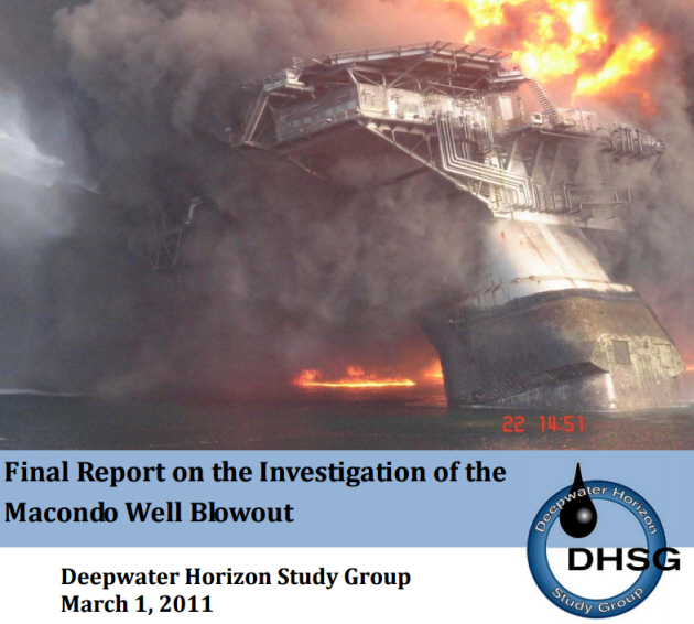
Final Report on the Investigation of the Macondo Well Blowout

The Deepwater Horizon Study Group (DHSG) was formed by members of the Center for Catastrophic Risk Management (CCRM) in May 2010 in response to the blowout of the Macondo well on April 20, 2010. This is another report and it might give you some different ideas about this accident.

Figure 4 - Final Report on the Investigation of the Macondo Well Blowout

Figure 4 – Final Report on the Investigation of the Macondo Well Blowout

There are some highlighted subjects as listed below;

Chapter 1 – Timeline to Disaster

The Marianas

The Deepwater Horizon

The Blowout

Post Blowout Shutdown Attempts

Chapter 2 – Analysis of the Blowout

Summary of Factors Leading to Blowout

Candidate Flow Paths to the Rig Floor

Phase 1 – Production Casing Design & Construction

Phase 2 – Temporary Abandonment

Phase 3 – Attempts to Control the Well

Chapter 3 – Insights

Introduction

Organizational Accidents Perspectives

Production versus Protection Insights

Chapter 4 – Going Forward

Introduction

Observations

Findings

Commentary

Recommendations

These are some images in this report.

Figure 5 – Location of Macondo Well

Figure 5 – Location of Macondo Well

Figure 6 Wellbore Schematic Comparison

Figure 6  Wellbore Schematic Comparison

The report here –  http://ccrm.berkeley.edu/pdfs_papers/bea_pdfs/dhsgfinalreport-march2011-tag.pdf

We wish these two important reports would be advantageous to you. Well control is one of the most critical part of drilling engineering and operation.

Hole Monitoring Procedures While Running Casing or Tubing

$
0
0

This is the example of hole monitoring procedure while running casing and this will give you some ideas only. You need to adjust it to suit with your operation.

hole monitoring while running casing

  • Perform pre-job safety meeting with personnel involved in operation.
  • A Full Opening Safety Valve (FOSV) and a closing handle with correction bottom connections that fit with of drill string which is being used must be available on the drill floor at all time. Driller must check this equipment. It must leave in an opened position. It may be required to have cross over from FOSV to casing connection.
  • The Driller is responsible for well monitoring while tripping. The driller has the right to shut the well in if there is an indicator of well control or any doubt while tripping out.
  • Trip sheet must be prepared with correct drill string/ tubular displacement.
  • The Driller is responsible for well monitoring while tripping. The driller has the right to shut the well in if there is an indicator of well control or any doubt while running casing or tubing.
  • Shut In Procedure Running Casing or Tubing for Well Control Situation must be posted in the driller cabin where the driller can see it easily at all time.
    • Note: shut in procedure depends on requirement on each company.
  • Kick detection devices as flow show, Pit Volume Totalizer monitor, and alarm must be tested properly and regularly.
  • Mud logger kick detection devices must also tested in the same way as rig instrumentation to confirm an accuracy and readiness.
  • Set the trip tank gain/loss and the flow show at required level.
  • Use mud pit to monitor the well if larger casing is ran. Use a trip tank to monitor the well if a smaller casing or tubing is ran. This depends on the rig system.
  • Track volume displacement with two separate systems if possible (one from the rig system and another one from mud logger system).
  • Verify all well control equipment is properly lined up to shut the well in.
  • Confirm the correct line up for well monitoring via a trip tank.
  • Confirm the correct line up from mud pumps to the rig floor.
  • Review shut in procedure while running casing or tubing.
  • Review any foreseeable issues with Toolpusher and Customer Representative
  • Ensure correct casing or tubing tally while running in hole
  • Trip sheets must be recorded every stand of casing / tubing ran. Assistant Driller has a responsibility to accurately fill a trip sheet while running casing/tubing.
  • Trip sheets must be kept in a tool pusher office after tripping operation completed.
  • While running casing/tubing, if the volume discrepancy is seen, Assistant Driller must inform Driller, Tool Pusher and Company Representative. The running casing/tubing operation must be stopped for further evaluation and a Full Open Safety Valve must be installed.
  • Ensure shut in while running casing/tubing procedure is posted on the rig floor closed to the driller console
  • While tripping, if the volume discrepancy is seen, Assistant Driller must inform Driller, Tool Pusher and Company Representative. The tripping operation must be stopped for further evaluation and a Full Open Safety Valve must be installed.


Pipe Blown Up While Pumping

$
0
0

Working with pressure is one of the high risk tasks in oil and gas industry because enormous force can damage equipment and harm people life. In this 15-second vdo, it shows how quickly thing can turn to be a catastrophic. You need to watch this.

What Can We Learn from This VDO?

pipe blown up

What wen well

  • No one around the pressure test area

What went wrong

  • Pipe blown up
  • No barrier tape around
  • Equipment damage
  • Potential to hurt personnel

What Should We Do To Work Safely With High Pumping Pressure?

  • Know the pressure rating of all equipment
  • Know the anticipated pressure for the operation
  • Ensure all equipment must be inspected as per manufactures’ recommendation
  • Good visual inspection of all equipment before starting the job
  • Ensure the right procedures are used to connect hoses, chick sands, clamps, etc
  • Inspect all hoses and ensure each connection is secured with secondary retention equipment.
  • Hammer union connections must be inspected by using “go/no-go” ring to confirm compatibility.
  • Barrier tapes must be used to barricade all potential hazard area
  • Announcement must be made prior to starting any high pressure operation
  • Chicksans must have a secondary retention that is strong enough to stop it from swinging if there is a sudden release of pressure (this is similar to what you see in this VDO).

secondary retention 1


  • Ensure the hose will not be located on the sharp edge because while pumping the line can rub against the sharp edge and it causes host burst.
  • Check type of fluid that will be pumped into the system to ensure that it will not cause any damages to the hose/piping.

What are your opinions?

Please feel free to share with us.

How To Determine Seriousness of Drops Incident By Using the Drops Calculator

$
0
0

Drop incident is one of the worst incidents in oil and gas industry and DROPS is a company which comes up with the Drops Calculator.

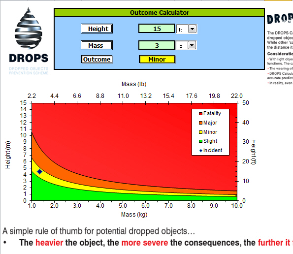
For example, you want to know what the potential hazard classification should be if 3 lb of object drops from 15 ft height. This is the Excel based program that gives you a benchmark about the classification of the potential consequences of a dropped object.

Drops Calculator FB

Let’s take a look how to use it

First of all, please download the DROPS calculator here – http://www.dropsonline.org/assets/documents/Dropped-Object-Consequence-Calculator-Nov-20111.zip

Ref – http://www.dropsonline.org/resources-and-guidance/drops-calculator/e-drops-calculator/

You will receive Dropped-Object-Consequence-Calculator-Nov-20111.zip. Then unzip the file and you will get
Dropped Object Consequence Calculator – Nov 2011.xlsm

If you see the screen like this (Figure 1), you can click “Enable Editing”.

Figure 1 - Enable Editing

Figure 1 – Enable Editing

You need to “Enable Content” in order to run a macro for this file.

Figure 2 - Enable Macro

Figure 2 – Enable Macro

Input parameters of dropped object. For this example, the dropped object weight is 3 lb and it drops from 15 ft height. The incident classification is Minor.

Figure 3 – object 3lb drops from 15 ft height

Figure 3 – object 3lb drops from 15 ft height

You can select unit of weight between lb and kg and unit of height between ft and m.

Note – Four classifications are as follows according to DROPS;

SLIGHT – A First Aid Case. No or limited injury. Treatment may be limited to first aid.

MINOR – A Recordable Incident. A Work-related injury that does not involve death, day(s) away from work, restricted work or job transfer, and where the employee receives medical treatment beyond first aid.

MAJOR – A Lost Time Incident (LTI). Non-fatal traumatic injury that causes any loss of time from work beyond the day or shift it occurred. Also referred to as Day Away From Work Case (DAFWC).

FATALITY – Death resulting from an injury or trauma.

Well Control Procedure for Non-Shearable String

$
0
0

There are many cases when non-shearable string is across the BOP therefore blind shear rams will not be able to shear the string to secure the well if needed. The special procedure must be in place to deal with this situation. This is an example of well control procedure for non-shearable string. If you want to use it for your rig, it must be modified to match with your rig operation.

Well Control Procedure for Non-Shearable String FB

  • Define which equipment is unable to be sheared such as BHA, thick wall drill collar, testing tool, downhole pump, etc. This step should be done ahead of the time.
  • Perform pre-job safety meeting with personnel involved in operation.
  • Before pulling out non-shearable string through BOP, flow check must be conducted to ensure a well condition.
  • Driller must ensure well static before pulling out.
  • Driller must ensure all line up for shut line is correct.
  • Shut in criteria if the well control indicator is seen.
    • If the risk is acceptable, pull the string out of the hole and shut the well in using blind or blind/shear rams. If this method is not applicable, another option is to make up a shearable string as drill pipe and run in hole. Then shut the well in using annular preventor or rams preventor.
    • If the risk is not acceptable, stab full opening safety valve and shut the well in via annular preventor. It might be possible to close rams if size of rams match with the non-shearable string. Driller must ensure the correct space out to prevent closing the BOP (annular or rams) on non-slick surface.

These procedures will be followed if the well is unable to be secured from the steps above.

Drop Drillstring During Tripping Operation

  • Lower the string close to the rotary table
  • Close Annular Preventer
  • Tie a rope on the elevator latch
  • Lower the block and takes the weight off the elevator.
  • Pull the rope to unlatch the elevator
  • Open Annular Preventer to drop the string
  • Shut the well in via blind/blind-shear rams

Drop Drillstring If The String Is Made Up To Top Drive

  • Lower the string close to the rotary table
  • Set slips and break the connection at top drive for one turn
  • Pick up and remove slips
  • Close Annular Preventer
  • Break out the top connection as fast as you can until the string is sceptered from top drive.
  • Open Annular Preventer to drop the string
  • Shut the well in via blind/blind-shear rams

Volumetric Well Control Example Calculations

$
0
0

This example demonstrates the calculations and the steps of the volumetric well control which will help you understand about what calculations according to the volumetric procedures.

volumetric Calculation FB cover

Gas kick at the bottom but unable to circulate due to drillstring plugged off. The well control information is listed below;

  • Pit gain = 10 bbl
  • Shut in Drill Pipe Pressure = 0 psi (drillstring plugged)
  • Shut in Casing Pressure = 400 psi
  • Current mud weight = 11.0 ppg
  • Casing shoe depth = 6,000’MD/6,000’TVD
  • Hole TD = 9,000’MD/9,000’TVD
  • Hole size = 12.25”
  • Casing ID = 12.5”
  • Drill pipe size = 5”, 19 ppf
  • BHA consists of 6.5” drill collar
  • Length of BHA = 800 ft
  • Average pipe per stand = 94 ft

Basic RGB

Figure 1 – Well Information

The volumetric well control will be utilized in order to bring gas up to surface while maintaining bottom hole pressure almost constant.

Safety Factor and Pressure Increment are 100 psi.

Assumption: Gas kick at the bottom

Mud Increment

Mud Increment (MI) is calculated by the following equation

MI equation


Where;

MI = Mud Increment (MI), bbl

PI = Pressure Increment (PI), psi

ACF = annular capacity factor between casing and drillstring, bbl/ft

MW = mud weight, ppg

ACF = (12.52 – 52) ÷ 1029.4 = 0.1275 bbl/ft

MI equation 2


Mud Increment (MI) = 22.3 bbl

Volumetric Control Procedures

  1. We determine the Safety Factor (SF), Pressure Increment (PI) and Mud Increment (MI).
    • Safety Factor (SF) = 100 psi
    • Pressure Increment (PI) = 100 psi
    • Mud Increment (MI) = 100 psi
  2. Wait for casing pressure to increase by Safety Factor (SF) + Mud Increment (MI). For this case, we will wait until casing pressure reaches 600 psi (400 + 200). At this point, the over balance is 200 psi and gas migrates up from the bottom of the well.

Figure 2 - Allow Casing To Increase by SF + PI

Figure 2 – Allow Casing To Increase by SF + PI

Basic RGB

Figure 3 – Diagram Showing Gas Migration and Casing Pressure Increases

  1. Hold casing pressure constant and bleed off fluid volume by Mud Increment (MI). For this case, the volume of mud bled off is equal to 22.3 bbl. At this point, the over balance will be 100 psi.

Figure 4 - Bleed of Mud Volume by MI

Figure 4 – Bleed of Mud Volume by MI

Basic RGB

Figure 5 – Diagram Showing Bleeding off Mud Volume by Mud Increment (MI) Holding Casing Pressure Constant

  1. Shut the well in and wait until casing pressure increases by Pressure Increment (PI). At this point, casing pressure will increase to 700 psi and the overbalance of the wellbore is 200 psi.

Figure 6 - Allow Casing Pressure to Increase by Pressure Increment (PI)

Figure 6 – Allow Casing Pressure to Increase by Pressure Increment (PI)

Basic RGB

Figure 7 – Diagram Showing Gas Migration and Casing Pressure Increases

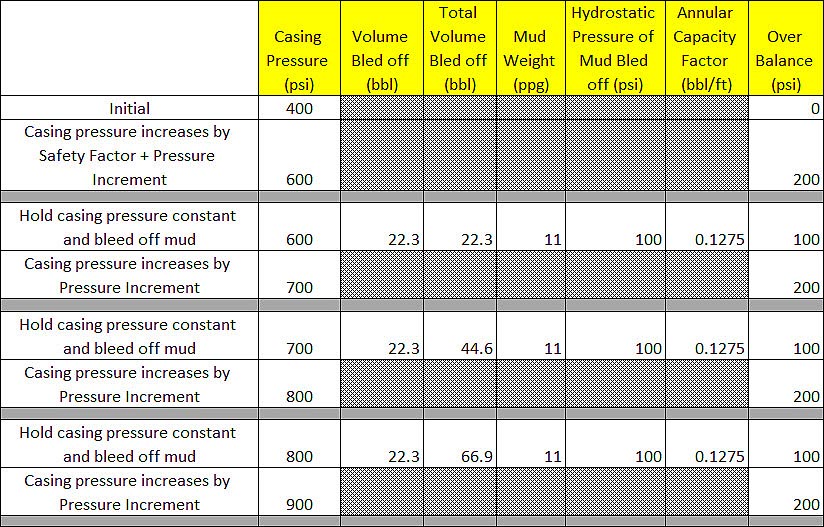
  1. Repeat step#3 and step#4 until gas at surface (casing pressure stops increasing) or the well kill operation can be performed with an alternative method. For example, if the pumps fails and the volumetric well control method is selected because you don’t want the bottom hole pressure increase too much. When the pumps are back in a service, other well control methods as driller’s method or wait & weight can be performed. As per this example, we will perform the volumetric well control until gas at surface.

Figure 8 – Table Demonstrates Steps of Volumetric Well Control

Figure 8 – Table Demonstrates Steps of Volumetric Well Control

Referring to Figure 8, you can see that casing pressure is allowed to increase and the mud is bled off to compensate increase in bottom hole pressure. Figure 9 is a summary chart showing casing pressure and over balance during the volumetric operation. The overbalance of the well bore is maintained between 100 psi to 200 psi. In some situations when there is a chance to break formation at a casing shoe, you might consider selecting the lower figure of safety factor as 50 psi.

Figure 9 - Pressure Summary

Figure 9 – Pressure Summary

Reference books: Well Control Books


Ouija Board Directional Drilling Excel Spreadsheet

$
0
0

Ouija Board is a method that directional drillers use to calculate inclination and azimuth at the bottom or distance and tool face to drill at required direction. Figure 1 is an Ouija board.

Figure 1 - Ouija Board

Figure 1 – Ouija Board

I got an excellent Excel Spreadsheet that will help you calculate the direction at bottom, distance to drill and tool face. I will give you a couple of examples to give you an idea what results from the Ouija Board spread sheet.

These are current directional parameters

Current Inclination (degree) = 28.00

Current Azimuth (degree) = 230.00

Distance to Drill (ft) = 60.00

Dog Leg Interval (ft) = 100.00

Average Tool Face = 30.00

Average DLS (degree/100 ft) = 6.00

Result is “Inclination and Azimuth on Bottom”.

Inclination on Bottom (degree) = 31.17

Azimuth on Bottom (degree) = 233.31

You can use this part to project the inclination and azimuth at the bottom.

Figure 2 - Inclination and Azimuth on Bottom

Figure 2 – Inclination and Azimuth on Bottom

This is another example below.

Current Inclination (degree) = 32.50

Current Azimuth (degree) = 90.00

Required Inclination (degree) = 35.00

Change in Azimuth (degree) = 5.00

Dog Leg Interval (ft) = 100.00

LEFT or RIGHT (L,R) = L

Average Dog Leg (degree/100 ft) = 6.00

Result is “Distance to Drill and Optimum Tool Face”.

Distance to Drill (ft) = 64.35

Optimum Tool Face (degree) = 52.19 L

Figure 3 - Distance to Drill and Optimum Tool Face

Figure 3 – Distance to Drill and Optimum Tool Face

If you are interested in this Excel Spreadsheet, please download here – https://oilfieldmania.files.wordpress.com/2015/07/ouija-board-final.xlsx

Using Hi-vis Sweep to Clean Hole while Drilling

$
0
0

Sweep is a mud which has higher rheology and/or more mud weight than current mud property. It is used to carry cutting that set at low side of a wellbore and it is widely used for Sea water drilling.

sweep-for-hole-cleaning

These images show how sweep works.

Cutting at the low side of the well bore (image below)

1-cutting-low-side

Sweep is pumped (image below).

2-sweep-is-pumped

Hole is clean (image below).

3-hole-is-clean

This is a real case which will show you how the sweep helps hole cleaning.

Information

Drilling fluid – sea water

Sweep property:

Funnel Viscosity +/- 100 sec

PV = 25

YP = 34

Density = 10.0 ppg

Hole angle = 59 degree

Sweep volume = 50 bbl

Formation = sand stone, clay stone, clay, trace carbonate

Drilling parameters before pumping sweep

Pick up = 300 klb

Rotate weight = 250 klb

Slack off = 200 klb

Torque = 23,000 ft-lb

Drilling parameters after pumping sweep

Pick up = 280 klb

Rotate weight = 230 klb

Slack off = 1900 klb

Torque = 20,000 ft-lb

It is clearly seen that sweeping the hole helps hole cleaning.

Before (Image below)

before

After (Image below)

after

Do you have any experience about pumping sweep?

Please feel free to share with us in the comment section.

Oil and Gas Production Handbook Review

$
0
0

Today, we would like to recommend you to read this book – Oil and Gas Production Handbook which is one of the best free ebooks for oilfield personnel .

Oil and Gas Production Handbook

An Introduction to Oil and Gas Production, Transport, Refining and Petrochemical Industry

Edition 3.0 Oslo, August 2013

Håvard Devold

©2006 – 2013 ABB Oil and Gas

cover

In this ebook, there are several of topics covered in both upstream and downstream business. You will learn about oilfield from start (exploration) to finish (refinery) and it has an interesting topic about unconventional resource.

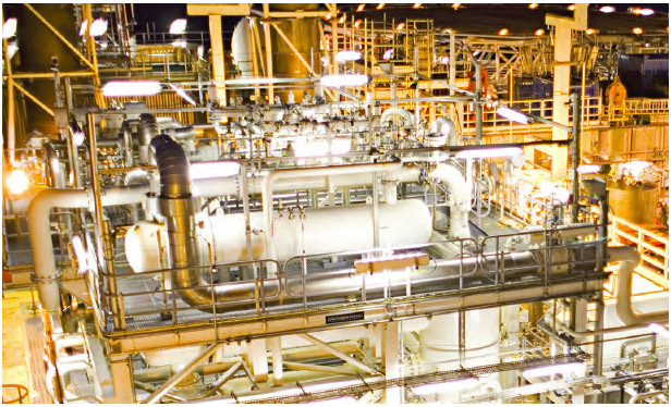
These images below are captured from this ebook.

Figure-1-Reservoir

Figure 1 – Reservoir

Figure 2 - Gycol Generator

Figure 2 – Gycol Generator

Figure 3 - Transesterification

Figure 3 – Transesterification

You can see the all the details in this book from the table of content below;

1 Introduction

2 Facilities and processes

2.1 Exploration
2.2 Production
2.2.1 Onshore
2.2.2 Offshore
2.3 Upstream process sections
2.3.1 Wellheads
2.3.2 Manifolds and gathering
2.3.3 Separation
2.3.4 Metering, storage and export
2.3.5 Utility systems
2.4 Midstream
2.4.1 Gas Plants
2.4.1 Gas compression
2.4.2 Pipelines
2.4.1 LNG liquefaction and regasification facilities
2.5 Refining
2.6 Petrochemical

3 Reservoir and wellheads

3.1 Crude oil and natural gas
3.1.1 Crude oil
3.1.2 Natural gas
3.1.3 Condensates
3.2 The reservoir
3.3 Exploration and drilling
3.4 The well
3.4.1 Well casing
3.4.2 Completion
3.5 Wellhead
3.5.1 Subsea wells
3.5.2 Injection
3.6 Artificial lift
3.6.1 Rod pumps
3.6.2 ESP
3.6.3 Gas lift
3.6.4 Plunger lift
3.7 Well workover, intervention and stimulation

4 The upstream oil and gas process

4.1 Manifolds and gathering
4.1.1 Pipelines and risers
4.1.2 Production, test and injection manifolds
4.2 Separation
4.2.1 Test separators and well test
4.2.2 Production separators
4.2.3 Second stage separator
4.2.4 Third stage separator
4.2.5 Coalescer
4.2.6 Electrostatic desalter
4.2.7 Water treatment
4.3 Gas treatment and compression
4.3.1 Heat exchangers
4.3.2 Scrubbers and reboilers
4.3.3 Compressors, anti-surge and performance
4.4 Oil and gas storage, metering and export
4.4.1 Fiscal metering
4.4.2 Storage
4.4.3 Marine loading

5 Midstream facilities

5.1 Gathering
5.2 Gas plants
5.2.1 Gas composition
5.3 Gas processing
5.3.1 Acid gas removal
5.3.2 Dehydration
5.3.3 Mercury removal
5.3.4 Nitrogen rejection
5.3.5 NGL recovery and treatment
5.3.6 Sales gas specifications
5.4 Pipelines
5.4.1 Pipeline terminal
5.4.2 Gas Pipelines, compressor and valve stations
5.4.3 Liquid pipelines, pump and valve stations
5.4.4 Pipeline management, control and safety
5.5 LNG
5.5.1 LNG liquefaction
5.5.2 Storage, transport and regasification

6 Refining

6.1 Fractional distillation
6.2 Basic products
6.3 Upgrading and advanced processes
6.4 Blending and distribution

7 Petrochemical

7.1 Aromatics
7.1.1 Xylene and polyester chain
7.1.2 Toluene, benzene, polyurethane and phenolic chain
7.1.3 Benzene and styrenic chain, derivatives
7.2 Olefins
7.2.1 Ethylene, derivatives
7.2.2 Propylene, derivatives
7.2.3 Butadiene, butylenes, and pygas, derivatives
7.3 Synthesis gas (syngas)
7.3.1 Methanol based products
7.3.2 Ammonia based products

8 Utility systems

8.1 Process control systems
8.1.1 Safety systems and functional safety
8.1.2 Emergency shutdown and process shutdown
8.1.3 Fire and gas system
8.1.4 Control and safety configuration
8.1.5 Telemetry/SCADA
8.2 Digital oilfield
8.2.1 Reservoir management and drilling operations
8.2.2 Production optimization
8.2.3 Asset optimization and maintenance support
8.2.4 Information management systems (IMS)
8.2.5 Training simulators
8.3 Power generation, distribution and drive
8.4 Flare and atmospheric ventilation
8.5 Instrument air
8.6 HVAC
8.7 Water systems
8.7.1 Potable water
8.7.2 Seawater
8.7.3 Ballast water
8.8 Chemicals and additives
8.9 Telecom

9 Unconventional and conventional resources and environmental effects

9.1 Unconventional sources of oil and gas
9.1.1 Extra heavy crude
9.1.2 Tar sands
9.1.3 Oil shale
9.1.4 Shale gas and coal bed methane
9.1.5 Coal, gas to liquids and synthetic fuel
9.1.6 Methane hydrates
9.1.7 Biofuels
9.1.8 Hydrogen
9.2 Emissions and environmental effects
9.2.1 Indigenous emissions
9.2.2 Greenhouse emissions
9.2.3 Carbon capture and sequestration

10 Units

11 Glossary of terms and acronyms

12 References

13 Index

Download this ebook here – http://www04.abb.com/global/seitp/seitp202.nsf/0/f8414ee6c6813f5548257c14001f11f2/$file/Oil+and+gas+production+handbook.pdf

Avoid These Deadly Resume Mistakes to Get Perfect Oilfield Resume

$
0
0

With the current oil price environment today, it is very important that all oilfield job seekers are aware of the importance of writing quality oilfield resume.

By quality resume we mean those which are free of errors, illustrate ones accomplishments and they are targeted towards the oil and gas employers. Most of the job seekers tend to follow these guidelines. However, there are few mistakes which are overlooked easily while writing a resume.

In case you feel that you have written a perfect resume but you are still not receiving any interview calls, here are some deadly resume mistakes which you have probably made:

Poor Choice of Words

Poor choice of words is another very common mistake. While proofreading your resume, make sure to closely look at the wording you have used to describe the experience and do watch out for the homophones (the words which sound same but are differently spelled)
For example, one should be aware of the words like “two, to and too, “effected and affected”, and “there, they’re and their”. Checking for such common mistakes can prevent the resumes from going in trash.

Also make sure that you use the specific words on the resume. One should always avoid using the vague words like “many, some or varied”. For example, you should not say “improved company profits”, a better choice would be “increased the company profits by XYZ dollars.” You can see that replacing the word “increased” with improved, created much more impact.

Sharing Too Much Information

Remember that resumes are not meant to show one’s life history. Do not include information about marital status, religion, hobbies which are not related to the job, or number of children. These details should not be included in application and the interview process during the job search.

Using Wrong Tense

You should always use past tense, while talking about the previous experience. Make sure to use present tense when you are talking about the current position. It seems quite easy, doesn’t it? It surely seems like simple and easy grammar fix, but it is a common mistake made by many job seekers on the resumes.

Give attention to tenses used in your resume, while proofreading it. Read the resume loud multiple times and carefully think about which verb tense should be used in each section. You may well be surprised at mistakes you will find.

Putting the Skills Section at The End

Skills section is must for resumes in oil and gas industry. However, placement of the skills section is much more important. Skills section of the resume should be first thing which employers get to read. While writing your skills make sure to target the skills towards qualifications for position you are applying for. This will make your resume standout form the other applications

No links to The Social Media Profiles

In case you do not use LinkedIn or you do not have any digital portfolio, you missing a big opportunity of impressing the employers.

In order to make an outstanding resume, it is necessary to include the links to one’s social media profiles. You may place the URLs for the Twitter or LinkedIn accounts in header of the resume following the contact info.

Unnecessary Details Added

The employers do not care about all the jobs which you have had in your life. The only thing they care about is the experience related to that position for which you are applying.

For instance, if one is applying for the first job after college, one should not include the extracurricular activities from the high school or babysitting jobs during college years. Employers are only interested in learning about those jobs which can make one a good fit for offered position.

Additional Resources

Lubricate and Bleed Example Calculations

$
0
0

This example demonstrates the calculations and the steps of lubricate and bleed which will help you understand about what calculations according to lubricate and bleed procedures.

Example of Lubricate and Bleed Well Control Calculation

Gas kick migrates to surface underneath the BOP safely via Volumetric Well Control. The circulation is not possible due to drillstring plugged off therefore the decision is made to perform Lubricate and Bleed to kill the well. The well control information is listed below;

  • Shut in Drill Pipe Pressure = 0 psi (drillstring plugged)
  • Shut in Casing Pressure = 1,000 psi without any safety factor
  • Gas on surface at the BOP
  • Current mud weight = 11.0 ppg
  • Casing shoe depth = 6,000’MD/6,000’TVD
  • Hole TD = 9,000’MD/9,000’TVD
  • Hole size = 12.25”
  • Casing ID = 12.5”
  • Drill pipe size = 5”, 19 ppf
  • BHA consists of 6.5” drill collar
  • Length of BHA = 800 ft
  • Average pipe per stand = 94 ft
  • Wellhed rating = 5000 psi
  • BOP rating = 10,000 psi
  • Leak off pressure at shoe = 16.0 ppg
  • Estimated gas volume at BOP = 70 bbl
  • Estimated Bottom of gas = 549 ft

53 Example of Volumetric Well Control Calculation

Figure 1 – Well Information

Note: Before going onto detailed calculations, it is very important to explain to you that the Lubricate and Bleed method can kill the well or just reduce surface pressure. It is not 100% every time that the well will be successfully killed and you will see in the detailed calculations later.

The concept of Lubricate and Bleed is to remove gas at surface when the circulation cannot be performed. With this method, bottom hole pressure will be almost constant.  The mud will be pumped in to the well to increase bottom hole pressure and later gas will be bled off to compensate what hydrostatic pressure added into the system.

Lubricate and Bleed Calculations

Select Safety Factor (SF) – it is recommended to use a small and practical safety factor. For this calculation, the Safety Factor is 50 psi.

Select Pressure Increment (PI) – this is the hydrostatic of mud which is planned to lubricate into the well. Pressure Increment (PI) should be a small and practical figure so Pressure Increment (PI) for this calculation is 50 psi.

Calculate Lube Increment (LI)

Lube Increment (LI)is calculated by the following equation

LI calculation

Where;

LI = Lube Increment (MI), bbl

PI = Pressure Increment (PI), psi

ACF = annular capacity factor between casing and drillstring, bbl/ft, at surface.

ACF = (12.52 – 52) ÷ 1029.4 = 0.1275 bbl/ft

MW = mud weight, ppg

For this example, 14-ppg mud will be used.

** It is suggested to use higher mud weight as practical as possible. The reasons are small Lube Increment (LI) and higher change to kill the well.

LI calculation

Lube Increment (MI) = 8.8 bbl

Maximum Allowable Surface Casing Pressure (MASCP)

We need to know surface limitation prior to inject otherwise it can cause failure on surface equipment or break formation downhole and for this situation, Leak Off at show (16 ppg) is the limitation. In some cases, if you work on an old well, casing rating may be a limitation so you need to check and use the lower figure. For the worst case, we assume that gas will be fully replaced with kill mud (14.0 ppg).

MASCP is calculated by the equation below;

MASCP = Leak off Pressure – Hydrostatic Pressure

Hydrostatic Pressure = Hydrostatic Pressure from Kill Mud (14 ppg) + Hydrostatic Pressure from Current Mud (11 ppg)

Hydrostatic Pressure = (0.052 × 14 × 549) + (0.052 × 14 x 5,451)

MASCP = (0.052 × 16 × 6,000) – [(0.052 × 14 × 549) + (0.052 × 14 x 5,451)]

MASCP = 4,992– 400 – 3,118

MASCP = 1474 psi

Note: We don’t calculate the MASCP with only current mud weigh because it is not the worst case scenario.

Lubricate and Bleed Steps

  1. We determine the Safety Factor (SF), Pressure Increment (PI) and Mud Increment (MI).
    • Safety Factor (SF) = 50 psi
    • Pressure Increment (PI) = 50 psi
    • Lube Increment (LI) = 8.8 bbl
  2. Lubricate mud volume equal to Lube Increment (LI)

For this step, it will add safety factor into the well; however, if surface casing pressure already has safety factor, step#2 and step#3 must be skipped in order to prevent excessive safety factor which may cause fracturing shoe.

Volume gas is compressed by lubricated mud.

Volume of gas = Volume of gas at previous condition – Lube Increment (LI)

Volume of gas = 70 – 8.8 = 61.2 bbl

Pressure of compressed gas is determined by Boyld’s Law.

P2 = (P1 × V1) ÷ V2

Where;

P1 = Pressure of gas at previous condition, psi

V1 = Volume of gas at previous condition, bbl

V2 = Volume of gas compressed by lubricated mud, bbl

P2 = Pressure of gas compressed by lubricated mud, psi

This pressure represents casing pressure due to gas compression.

P2 = (1000 × 70) ÷ 61.2 = 1,144 psi

Overbalance of bottom hole pressure

Overbalance = P2 + Hydrostatic Pressure due to Lube Increment (LI) – P1 + Safety Factor

Where;

P1 = Pressure of gas at previous condition, psi

P2 = Pressure of gas compressed by lubricated mud, psi

Hydrostatic Pressure due to Lube Increment (LI) = Pressure Increment (PI)

Safety Factor = 0 psi

Overbalance = 1,144 + 50 – 1000 + 0

Overbalance = 194 psi

Figure 2 - Table Represents Pressure and Volume of Step2

Figure 2 – Table Represents Pressure and Volume of Step#2

53 Example of Volumetric Well Control Calculation

Figure 3 – Diagram shows mud lubricated into the well

  1. Bleed gas via choke until casing pressure reach the initial pressure in step#2

This step will establish a Safety Factor (SF) because surface pressure is bleed off to the original value and the only thing that adds into the wellbore is hydrostatic pressure from Lube Increment (LI) which is 50 psi for this example.

Overbalance of bottom hole pressure

Overbalance = Current Overbalance in step#2 – (Casing Pressure after Lubricating – Casing Pressure after Bleeding off)

Overbalance = 194 – (1,144 –1,000) = 50 psi

Figure 4 - Table Represents Pressure and Volume of Step3

Figure 4 – Table Represents Pressure and Volume of Step#3

53 Example of Volumetric Well Control Calculation

Figure 5 – Diagram shows bleeding gas out of the well


  1. Lubricate mud into the well equal to Lube Increment (LI)

8.8 bbl of mud is pumped and this will give 50 psi hydrostatic pressure increment.

Gas volume will be compressed by 8.8 bbl therefore the volume of gas will be reduced from 61.2 bbl to 52.4 bbl (61.2-8.8 = 52.4).

This pressure represents casing pressure due to gas compression.

Pressure of compressed gas is determined by Boyld’s Law.

P2 = (P1 × V1) ÷ V2

Where;

P1 = Pressure of gas at previous condition, psi

V1 = Volume of gas at previous condition, bbl

V2 = Volume of gas compressed by lubricated mud, bbl

P2 = Pressure of gas compressed by lubricated mud, psi

This pressure represents casing pressure due to gas compression.

P2 = (1000 × 61.2) ÷ 52.4 = 1,168 psi

Overbalance of bottom hole pressure

Overbalance = P2 + Hydrostatic Pressure due to Lube Increment (LI) – P1 + Safety Factor

Where;

P1 = Pressure of gas at previous condition, psi

P2 = Pressure of gas compressed by lubricated mud, psi

Hydrostatic Pressure due to Lube Increment (LI) = Pressure Increment (PI)

Safety Factor = 50 psi ** The safety factor is established from step#2 and step#3.

Overbalance = 1,168 + 50 – 1000 + 50

Overbalance = 268 psi

Figure 6 - Table Represents Pressure and Volume of Step4

Figure 6 – Table Represents Pressure and Volume of Step#4

53 Example of Volumetric Well Control Calculation

Figure 7 – Diagram shows mud lubricated into the well


  1. Bleed casing pressure until casing pressure is equal to casing pressure in step#4 before lubricating minus Pressure Increment (PI)

This step will intentionally reduce casing pressure which has the same value of Pressure Increment (PI) which is 50 psi for this case.

Casing pressure @ step#4 before lubricating = 1,000 psi

PI = 50 psi

Casing pressure after bleeding off = 1000 – 50 = 950 psi

Overbalance of bottom hole pressure

Overbalance = Current Overbalance in step#4 – (Casing Pressure after Lubricating – Casing Pressure after Bleeding off)

Overbalance = 268 – (1,168 –950) = 50 psi

Figure 8 - Table Represents Pressure and Volume of Step5

Figure 8 – Table Represents Pressure and Volume Bled off of Step#5

53 Example of Volumetric Well Control Calculation

Figure 9 – Diagram shows gas bled off to planned pressure

  1. Repeat step#4 and step#5 until gas is out of the annulus (well dead) or casing pressure increase to Maximum Allowable Surface Casing Pressure (MASCP)

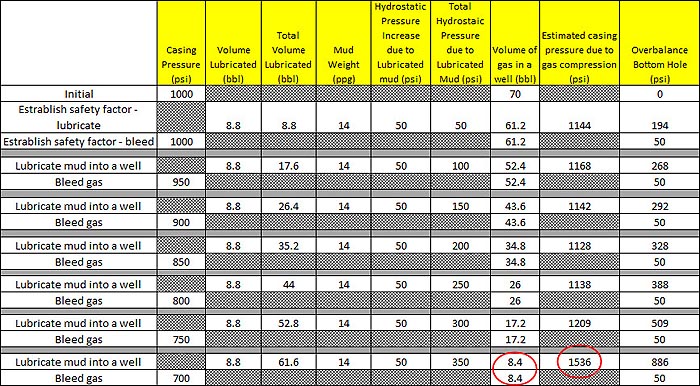
The table (Figure 10) shows all the required steps as per Lubricate and Bleed.

Figure 10 - Table Represents Pressure and Volume Bled off with Lubricate and Bleed

Figure 10 – Table Represents Pressure and Volume Bled off with Lubricate and Bleed

One thing that we would like to point out is at the last step the volume of gas left in hole is 8.4 bbl. Beyond this step is impossible because you need to lubricate a lubricate volume of 8.8 bbl and the casing pressure will exceed the MASCP. Therefore, the operation will stop at this point and casing pressure will be down from 1,000 psi to 750 psi with 50 psi overbalance.

Figure 11 – Not Enough Volume Gas Left in the Well to Lubricate

Figure 11 – Not Enough Volume Gas Left in the Well to Lubricate and Casing Pressure Exceeds MASCP

Thing to Remember

  • Lubricate and Bleed may or may not be able to kill the well but at least you can reduce surface casing pressure in a controlled manner.
  • Gas volume is getting smaller due to bleed off therefore it may reach the point that when you try to lubricate the mud, it will create very high surface casing pressure because of Boyle’s law. High surface pressure can cause either surface equipment damage or fracture formation at a casing shoe. It is very important to do the full step calculations in order to know when you will not be able to lubricate anymore. You need to know Maximum Allowable Surface Casing Pressure (MASCP) as your maximum lubricated pressure.

Reference books: Well Control Books

Review Fracking Primer EBook by API

$
0
0

Hydraulic Fracturing Primer is published by American Petroleum Institute (API) to help people understand about fracking correctly. In this ebook, it contains a technical detail about Fracking for non-technical people to understand the content. Additionally, there are tons of images, diagrams, charts, and illustrations in order to educate people.

Fracking-Primer-Cover

This is what you will learn from this book;

  • What is Fracking?
  • Energy and Opportunity
  • Shale Plays in the Lower 48 States
  • Securing Our Energy
  • Jobs and the Economy
  • What They Are Saying
  • Process, Safety, and the Environment
  • Drilling
  • Stimulation
  • State Regulation
  • Federal Regulation
  • Industry Standards, Federal Regulation
  • Water Protection
  • Water Usage
  • Water Treatment Technologies
  • Air Emissions
  • Methane Emission
  • Hydraulic Fracturing and Seismic Activity
  • Innovations Promote Safe & Environmentally Friendly Practices
  • Resources

These are some of images from this book.

Figure-1---US-shale-map

Figure 1 – US shale map

Figure-2---Hydraulic-Fracturing-Well-Schematic

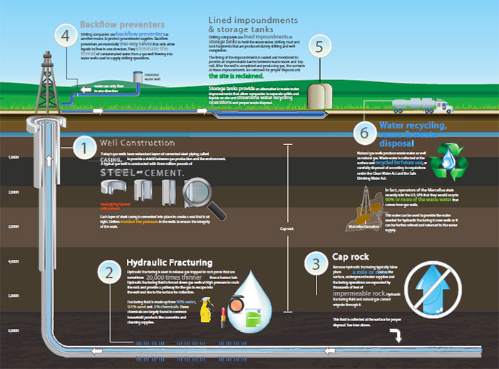
Figure 2 – Hydraulic Fracturing Well Schematic

Figure-3---Water-Treatment-Technology

Figure 3 – Water Treatment Technology

If you are interested in this ebook, please download from this link

http://www.api.org/~/media/files/oil-and-natural-gas/hydraulic-fracturing-primer/hydraulic-fracturing-primer-2015-highres.pdf

Only 21 Seconds Can Change Your Life – Fingerboard Incident

$
0
0

One of my colleague shared this vdo in the HES meeting and I was stunning on how quick of this incident happening. This is very short VDO only 21 seconds but it is worth to learn to prevent this same situation.

What was happened?

fiberboard-incident-no-play

The derrick attempted to move the air tuggers line which got caught in the fingerboard. He tried to move the line by applying force to move the line out and then the line came free and jumped from the fingerboard. However, the derrick man still held the line and he was pulled out of the fingerboard and fell down along the tugger line.

I don’t know much detail how he was doing after this but the points that I would like to share with you are as follows;

  • Always assess the situation prior to working on any task

  • Always have the safety harness tied with your body while working at height

  • Always be aware of surrounding and don’t become complacent because you have been working in the position for long time and you think you have a lot of experience on what you are doing

  • Always review work at height risk prior to and while working

What are your opinions?

Please feel free to share with us at the comment box below.


5 Ways NOT to Get the Attention of Hiring Managers in Oil and Gas Jobs

$
0
0

The increasingly competitive oil and gas career of today has made it quite difficult to stand out among large numbers of applicants all boosting same qualifications and skills. For this reason, the job applicants do everything in their capacity to attract the attention of hiring managers. It might sound great but as too much can be bad for anything.

All oilfield job candidates have same 3 goals: Capture the attention of a hiring manager, go good in interview, and land a job. But, in case you fail in first one, you will fail all of them.

5-Ways-NOT-to-Get-a-Hiring-Manager

Following are 5 don’ts, why they did not work and lastly what one should do.

Don’t#1: The candidate lit corner of the resume on fire in order to show the “burning desire” for job.

Reason why it did not work: Well, I guess we all know why the trick did not work; it is overly dramatic and dangerous too.

What you should do instead: You do not have to burn the resume in order to showcase the desire. Simply doing one’s homework on company along with applying what one learned to one’s own knowledge, experience and skills is enough to prove that you are interested in joining their company.

Don’t#2: The candidate showed photos of his relatives who have had worked for the company before.

Reason why it did not work: Having personal ties to the company can work to the applicant’s advantage but the eligibility of the applicant is purely dependent on skills, education, experience and personality. Showing the photos of your friends or relatives who have previously worked or are working at company does not highlight your qualifications.

What you should do instead: You can mention the named during the interview, as they can serve you as references. However, it is important that you do not rely on the connections for securing a job. So instead of name dropping, you should use those acquaintances, friends or family members as professional reference at the right time.

 Don’t#3: The candidate found where hiring manager was going for dinner and picked up the tab.

Reason why it did not work: The applicant might have done this with good intentions, nevertheless it’s a bribe and stalking was involved as well. This obviously cannot work in one’s favor. It can hurt the chances of getting job. Suppose you are able to get a job by bribing the hiring manager, would you really like to work in an organization which values status and money over experience and necessary skills? I don’t think so

What you should do instead: You should avoid saying or doing anything which can be considered as bribe. Focus on the intrinsic motivators instead of extrinsic motivators. You should try to persuade the hiring manager with your knowledge and skills related to job, and industry instead of picking up the tabs at five star restaurants.

Don’t#4: The candidate answered a phone call during his interview stating that it was another company wanting to discuss the job offer from other oilfield companies.

Reason why it did not work: It is very important that mobile devices are turned off in job interviews. It is very rude and unprofessional to use your phone during the interview. Moreover, the tactic is quite insulting. It is very unlikely that an interviewee would receive call about some other job offer while giving an interview.

What you should do instead: You Should mention the other companies in which you have applied unless you are asked by the hiring managers. Instead, you should focus to attract the hiring manager with the samples of the previous work which you have done and the evidence of the past successes you’ve had. The evidence of the success and skills will speak much louder than “job offers” from other companies.

Don’t#5: The candidate made his daughter call hiring manager before interview in order to thank the manger “for giving job to her dad.”

Reason why it did not work: Although the candidate’s attempt to land the job is not monetary, but it can be considered as bribe. The candidate strangely used daughter in order to persuade hiring manger even before the interview.

Every candidate who applies for a job has his own reasons for needing or wanting a job, but it should be remembered that personal reasons of candidates are not relevant to the success of the organization and therefore they are irrelevant to the hiring mangers as well.

What you should do instead: The first thing is to never assume that job is yours. The second thing is to save the reasons which you have for wanting a job, until you are asked by the interviewer that why you are interested in that position or/and that company. Always remember that the sole job of hiring manager is to hire on the basis of potential and skills.

Additional Resources

Vibration Mechanisms In Drillstring by SperrySun

$
0
0

Vibration in drillstring is one of major downtime associated with drilling operation. Therefore, it is very important to learn and understand what each vibration mechanism is. This VDO created by Sperry Drilling Services well explains various of vibration modes that is happened downhole with the drillstring. You can watch the VDO here and we also provide full VDO transcription to help learns get more understanding about the content if the learners cannot catch all wordings from this VDO.

Full VDO Transcript

Spery-Vibration-mechanisms-Explained-fb

At Sperry where time is money, improving drilling performance starts with the integrity of the drill string. A recent worldwide survey puts the cost of down time to the industry at $31 billion with down hole failure as a significant percentage. Since vibration at high shock loads are a major factor in down hole tool failure and can also cause ring repair and hole problems, prevention is a very high priority.

When you look at these obvious consequences of drilling vibration and high shock loads, it’s not surprising how much you can boost overall drilling performance when you use a proactive approach to preventing or reducing these destructive forces. Since the first step in solving a problem is giving it a name, let’s focus on how we describe these forces. There are three modes of vibration; axial, lateral and torsional – which are the directions the drill string moves when it runs into trouble down hole.

In the axial mood, the vibration is longitudinal motion along the drill string resulting in varying tension and occasionally compression tension reversals.

In the lateral mode, the vibration is side to side motion that causes flexing or bending of component, again leading to stress reversals where one side of the pipe will be in a different tensional state than the other.

In the torsional mode, the vibration is resistance to rotation resulting in twisting as torque is applied to overcome resistance. So that’s how the drill string reacts if it runs into any of the nine different kinds of trouble we called vibration mechanisms.

The first one called stick-slip is irregular drawstring rotation; the vibration mode is torsional as the bit stops rotating momentarily at regular intervals causing the string to periodically torque up and then spin free at 2 to 15 times the average surface rpm, causing severe damage to the bit and BHA.

The second mechanism is called Bit Bounce; it’s the axial or longitudinal vibration of the drill string that typically happens with free Cone bits and hard rock formations. Bit bounce damages the drill bit cutting structure, bearings and seals, and results in flexing of the drill string causing even more damage from axial and lateral shocks.

Next is Bit Whirl; it occurs when the bit has cut itself a hole larger than its own diameter, allowing it to wander around in the wellbore instead of simply rotating around its natural center. Excessive side cutting creates an over gauge hole that in turn increases the tendency for the bed and BHA to continue whirling.

Number four mechanism is BHA Whirl; the eccentric rotation of the BHA around a point other than its geometric Center in a complex motion generating lateral displacements, shocks and increased friction against the wellbore, occurring as forward or backward whirl is the mechanism that constitutes the main cause of BHA and down hole tool failure. Next, lateral shocks; describes what happens when the vibration mechanisms of bit bounce, BHA Whirl or motor coupling become so extreme. They cause the release of energy builds up in the drill string through several large lateral shock impacts. Unlike BHA Whirl, where the motion settles to a steady state, in this case the lateral shocks occur randomly. Torsional resonance is specifically drill collar torsional resonance and causes of juddering vibration of the drill string. It typically occurs in very hard rock being drilled with the PDC bit.

Parametric Resonance is our name for the severe lateral vibrations generated by axial vibrations, caused by the interaction of the bit with the formation which results in fluctuations of weight on the bit. Bit Chatter is the high-frequency lateral and torsional vibration of the bit and BHA, caused by a slightly eccentric bit rotation where there is cutting interference with the bottom hole cutting pattern.

The cutters right up under the ridge between previously cut grooves and then draw back into the groove. Modal Coupling describes vibration occurring at all three modes; axial, torsional, and lateral simultaneously. It creates axial and torsional oscillations and high lateral shocks along the BHA. The most extreme form of vibration is usually results from failing to control one of the other vibration mechanisms.

Okay, now that we’ve identified the problem, we’re going to do about it? The solution starts with sensors that are able to measure the different modes of vibration and enable us to identify the different mechanisms. Accelerometer can be mounted in tools to measure axial and lateral shock in vibration. Sensors that measure changes in down hole rotary speed and changes in torque at surface can be used to identify torsional vibration. Sperry drilling services extensive experience with our wide range of vibration tools has proven that with all the factors and variations that affect vibration, real time monitoring is the key to managing the problem. We also offer software that provides an automatic recalculation of the natural and harmonic resonance frequencies of the BHA. This is based on change in weight on bit, hole angle, dog legs severity, hole size and mud weight, and reflects the actual drilling conditions encountered. All of the critical rpm values can be displayed at the rig floor, so this form of vibration can be minimized. A vibration monitor analyzes measurement from the down hole tools, can automatically determine the vibration mechanism and provide advice on changing drilling parameters to stop it. of course measuring and responding to the complex array of vibrations while drilling is a real challenge, that’s why Sperry provide specialist from the applied rolling technology service or ADT to help you determine the vibration mode and mechanism that’s causing your problems and come up with ways to mitigate it.

The ADT optimization service will also identify ways of preventing the vibration from occurring on subsequent bit runs or wells. By modeling the expected conditions in making the correct measurements while drilling, we can virtually eliminated vibration. This significant step toward optimizing the   drilling process can save the industry a huge chunk of the 31 billion dollar cost of downtime.For more information, please contact sperry@halliburton.com

Review Offshore Book 2014 – an overview of the offshore oil & gas industry

$
0
0

The “Offshore Book – an overview of the offshore oil & gas industry” is one of the best ebook about offshore oil and gas industry. This book is belong to http://www.offshoreenergy.dk/.

offshore-book

This book is an introduction to offshore oil and gas industry and it is written in a simple language in order to educate people about offshore industry. This book is a very good start for new engineers, university students, non-technical personnel; however, there are some topics that is still excellent for experience workforces. The content is based on North Sea and Danish conditions but it is still applicable for any offshore workplaces.

Note from preface

“OffshoreBook Oil & Gas is 3rd edition of the OffshoreBook edited by the Danish knowledge center and innovation network Offshoreenergy.dk in collaboration with external editors. Offshoreenergy.dk wishes to thank all members who have contributed to the book and especially those who have helped in the editing work including, but not limited to: Ramboll Oil & Gas, DONG Energy, Wintershall, Semco Maritime, MacArtney, SubC Partner, ABB, GEUS, the Danish Energy Authority, Aalborg University Esbjerg, the University of Southern Denmark and the technical school in Esbjerg – EUC Vest.”

What will you learn from this book?

These are content from the book that you may be interested in .

  • Health, Safety and Environment – HSE
  • Basic Information about Oil and Gas
  • Reservoir – Geology and Exploration
  • Drilling Operations
  • Offshore Structures
  • Subsea Technology
  • Production of Oil and Gas
  • Pipelines
  • Oil and Gas Activities in the North Sea
  • Oil and Gas Production in Denmark
  • Decommissioning
  • Upstream and Downstream Logistics
  • Downstream
  • Education and Training in Denmark

Sample of Various Images from This book

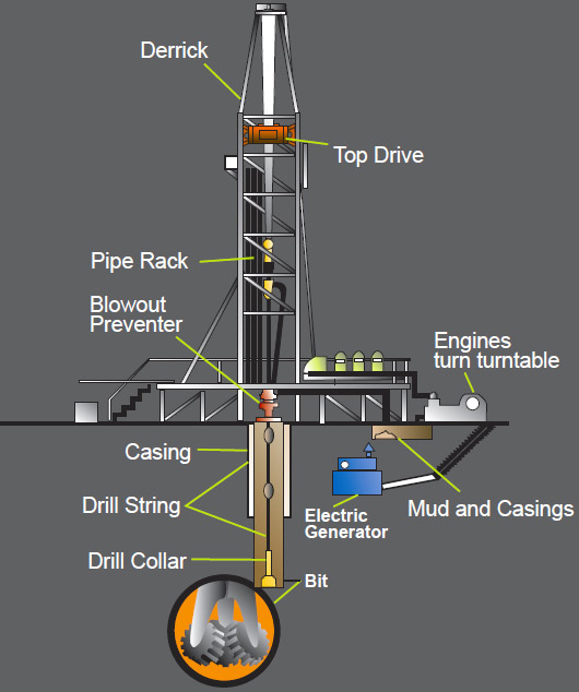
 1-process 2-offshore-rig 3-drilling-rig


Where can you download?

Download the ebook here – http://www.offshoreenergy.dk/Files/Filer/Publications/OffshoreBook_2014.pdf


What is the difference between a hazard and risk?

$
0
0

You may have heard about hazard and risk all the time while you are working either in the office or in the field.

Do you really know what the differences between these two terms are?

hazard-and-risk

 Is it easy question?  A lot of the time hazard and risk are freely used as a same thing however it is apparently not.  In oil and gas industry, these two terms are very vital to know and understand.

There are some confusion between hazard and risk.

Hazard can be identified as anything that has potential to cause harm to people, environment, or properties.

Risk is a potential (likelihood and severity ) that hazard will cause harm or damage to people, environment, or properties.

For example, you plan to climb up the ladder so the ladder is a hazard. Climbing up the ladder and falling off is the risk for this task.

Climbing up

Climbing up

Additional example, if you travel by the helicopter to the rig. The helicopter is the hazard and flying the plan in a thunder storm and cashing is a risk.  Last example, you use the hammer to do the job. The hammer is a hazard but using it and injure yourself is the risk.

Now you get an idea about hazard and risk.

Then the question is how to assess it. We will demonstrate you a simple way to illustrate how to assess it.First, we assess how likelihood someone will expose to it. The likelihood depends on probability and frequency of exposure to a hazard. We also assess the likely outcome, the severity or range of potential consequences resulting from the hazard.

Snake in a box

Snake in a box

For example, if we have a snake contained in a closed box, rating the hazard of the snake against the possibility and severity scale will show that the harm to a human life is small. However, if the snake is outside of the box, the possibility and severity change so for this case the snake will be likely danger human life.

Note: we will go through the detailed risk assessment processes later.

Shock and Vibration in Drilling VDO

$
0
0

This is one of excellent VDO demonstrating shock and vibration in the drillstring by Schlumberger. In this VDO, you will learn about mechanisms of shock and vibration, types of whirls and how these will damage your drillstring and BHA. Moreover, we provide the VDO transcript to help you get more understand about the content of this VDO as well.

Full VDO Transcript

shock-and-vibration-in-drillstring-SLB

As you know both shock and vibration are prime culprits in many drilling problems, today we are going to discuss how to minimize their effects and thereby improve drilling performance. Shock in a drilling environment is the sudden input of energy from impacts of the bit, BHA or drill pipe with the wellbore. Vibrations can result from the shocks. Rapid and continuous vibrations result in fatigue of the drill string connections to the point of twisting off. This is why many drill string failures are the result of accumulative fatigue due to vibration and have regular inspection periods. Shocks are measured in G’s by an accelerometer. 1G equals the force of gravity. Shock magnitudes registered via down hole tools can exceed 200G’s.

The severity of a shock depends on three parameters;

1- the magnitude of the shock,

2- the duration or length of time of the shock and

3- the frequency or number of shocks.

Magnitude is that a force the tool sees when impacts the borehole well. Duration measure how long the shock last in seconds. Frequency is the number of times the tool seize a shock greater than the accelerometer’s threshold. Shock and vibration and poor drilling mechanics can adversely affect ROP, slowing the drilling process.

So how do we detect potentially harmful shock and vibration? Surface and down hole data in both depth and time formats are used to diagnose down hole conditions. Looking at the drill string and bit after the run will also help you determine the severity and type of shock and vibration.   Schlumberger measures lateral shocks and all of their tools; these tools have shocks sensors that measure lateral vibration shocks with magnitudes greater than 50G’s. Our discussion will look into six BHA dynamic motions; axial, lateral, torsional, BHA Whirl, Stick-slip and eccentric. These can exist separately or can be present together. Proper identification of the vibration mode is essential in order to recommend the correct cure.

Axial shocks arise from movement of the drill string along the axis of the drill string. in the most severe form, it is sometimes referred to as a bit hopping or bit bounce. However in most cases, there is not enough force to allow the drill string to come up the bottom and bounce. Instead the shocks are transmitted up the drill string which harmonically increases and decreases the weight on bit.The consequences of axial shocks could be broken bit teeth, damaged down hole tools and slowed ROP.

Lateral shocks result from lateral motion of the BHA in one side of the well bore to the other, causing it to bounce randomly against the sides of the bore hole walls. Torsional shocks result from the momentarily slowing down and stopping of the drill string which occurs when the bit digs into the formation deeply enough to slow it down relative to the drill string or when destabilized into the formation. This causes a whirling effect on the drill string which can fatigue the drill string and BHA.

BHA Whirl is very complex or exists as a result of under-stabilized drill string that forces acting on the BHA such as rotating, resonance rpm on large bore hole. Whirl occurs most frequently but is not limited to near vertical walls. It occurs when there is an side wave or lateral movement in the BHA contacting the walls. In the video, we see a rolling shaft test with BHA component mounted horizontally or anchored at each end of rotating.

There are three main types of BHA whirls; Forward, Backward and Chaotic Whirl. Forward whirl is when the BHA robs the formation along the same part of the collar as the drill string rotates. If the formation is abrasive, excessive wear will occur along the part of drill collar that rubs the formation this wear is seen as plat box one side of drill collar or as a single worn blade or stabilizer.

In Forward Whirl, the BHA still rotates in the same direction as the drill string. Forward Whirl can destroy bits and BHAs. Backward Whirl is very similar to Forward Whirl except friction between the formation and BHA is greater. This increased friction results in increased torque on the BHA, which causes the BHA to rotate in the opposite direction of the rotation of the drill string. If whirling is backwards, then the collar connections can flex and fatigue at a very fast rate, resulting in accelerated fatigue cracking, washouts and possible twist offs.

In Chaotic Whirl, there is no preferential side of the collars of BHA contacting the formation. The torque will be above average along with the lateral vibration and shocks. Chaotic whirl can occur when changing rotary rpm to try and address forward or backward whirl. Bit whirl is associated with PDC bits because of their aggressive side cutting action on harder rocks and near vertical holes. It is caused by non-symmetric cutting action of a real formation that displaces the bit from its center of rotation, and then allows the bit to move. Verification of shock and vibration can often be obtained by examining the bit after the trip. When dealing with BHA whirl, it is sometimes necessary to stop drilling completely to cure it- depending on the severity of the shocks and difficulties with drilling.

Stick-slip is a non-uniform rotation of the drill string. This is the rotational slowing down and acceleration of the BHA. In extreme cases, the BHA can stop, even reverses its direction. During drilling, friction builds up causing the BHA to momentarily turn at a slower rate than the surface pipe or even stop. As this happens, the string stores the energy imparted by the rotary of top drive in the drill string, excess energy builds up, the friction slowing BHA rotation will be overcome. When the stored rotation since it is now going to beyond the number of rotation the rotary has made, it will now spin backword for short period.

When this happens, an inadvertent unscrewing of the connector can occur. Our review of shocks and vibration effects on drilling is a good starting point for your understanding of the issues raised this phenomenon in the drilling environment. Schlumberger wants you to develop your knowledge of these issues, how to detect them and how to mitigate them. These different types of shocks occur simultaneously, creating serious drilling problems which often requires drilling to stop and then restart. Careful planning, execution and post-drive analysis will often reduce the hazards of these shocks and vibrations. We hope this presentation will assist you in this endeavor. Thanks for your attention

Please feel free to share if you think this will be useful for other people.


Viewing all 497 articles
Browse latest View live


<script src="https://jsc.adskeeper.com/r/s/rssing.com.1596347.js" async> </script>