Quantcast
Channel: Drilling Formulas and Drilling Calculations
Viewing all 497 articles
Browse latest View live

Drill String Components – VDO Training

$
0
0

This is a great VDO Training about drill  string components. We also added the detailed transcripts so you can learn from the VDO effectively.

Please give us comments if you think this is useful for you.

Transcription of Drill String Components 

drillstring component

There are many components that make up the drill string as shown in this graphic. Drill pipe is a strong but relatively lightweight pipe. Crew members attach it to a top drive or Kelly. Drill pipe forms the upper part of the drill string. Usually the drill pipe rotates which also rotates the bit. Each section of pipe is called a joint. Crew members screw together or make up several joints and put them in to the hole as the bit drills.

Drill pipe as well as other tubulars can be specified according to these characteristics;

  1. Diameter
  2. Grades or strength
  3. Weights of steel
  4. Length

The diameter, weight and strength used depends on the size of the hole, the depth of the well and the well properties.  Here is a typical oil field tally book. Many of these have sections in them which show standard drill pipe specifications. Drill pipe comes in three ranges of length.  Range one is 18 to 22ft, or 5.5 to 6.7m. Range two is 27-30ft or 8.2 to 9.1 meters. And range three is 38 to 45ft or 11.6-13.7m. The most common length is range two, 27 to 30ft or 8.2 to 9.1m.

Since a hole may be thousands of feet deep, crew members may screw together hundreds of joints of pipe. Drill pipe diameter can be as small as 2 and 3/8in or 60.3mm. This size weight 4.85 pounds per foot or 7.22kg per meter.  It can be as large as 6.58 in or 168.3mm this pipe weighs about 27.7 pounds per foot or 41.21 kg per meter. However 5 in 127mm drill pipe is one of the more common sizes. It weighs 19.5 pounds per foot or 29.01 kg per meter.  Normal drill pipe grades are E75, X95, G105 and S135. S135 is the strongest.

The rig crew makes up drill pipe using threaded sections at each end of the drill pipe. These threaded sections are tool joints. The female tool joint is the box end of the drill pipe. The male tool joint is the pin end. Tool joints come in seven sizes and types. Tool joint threads are rugged because the crew makes them up and breaks them out over the drilling process.

But they have to take care not to damage them. Proper care and handling of drill pipe and other royal field tubular can prevent corrosion in the life of the well. Crew members make up heavy wall drill pipe in the drill string below the drill pipe. Heavy walled drill pipe, also called heavy weight drill pipe, is made up between the drill pipe and the drill collars. Heavy wall drill pipe is used to provide a transition between the limber drill pipe and the drill collars which are quite stiff.  The use of heavy walled drill pipe reduces the stress that stiff drill collars put on the drill string.

As a result, heavy walled drill pipe reduces the fatigue on the regular drill pipe. It also helps keep the drill pipe in tension. And may sometimes provide weight on the bit just like drill collars do just like in directional drilling. Heavy walled drill pipe or heavy weight drill pipe has thicker walls and longer tool joints than standard drill pipe. The longer tool joints reduce wear on the pipes body, they keep the body away from the side of the hole. The wear pad also prevents wear, it keeps the middle of the pipes body away from the side of the hole.

Spiral heavy walled drill pipe is another type of heavy walled drill pipe. Spiral heavy walled drill pipe has a spiral grove in the body. Regular heavy wall drill pipe has no grove but spiral heavy walled pipe has no drill pad. When spiral heavy walled pipe contacts the side of the hole, only a small part of the pipe body actually touches it. In fact only the part of the pipe body between the spiral grove touches it. The groove does not touch the wall of the hole thus reducing the surface contact area. Reducing the surface contact area helps prevent the pipe from sticking.

Crew members make up drill collars at the bottom of the drill string. Drill collars have thick walls and are very heavy. They put weight on the bit to make the bit’s cutters bite into the rock and drill. Drill collars range in diameter from three to twelve inches or 76.2 to 304.8 mm. they range in weight from 650 to 11500 pounds or 300 to 5100 kilograms. This particular 6 in drill collar weighs about 2700 pound, 1225kilograms. Since the crew usually installs several drill collars, you can see that a bit requires a lot of weight to drill properly. How much weight depends on the type of formation and the size and type of bit and it can be several thousands of pounds.

Drill collars are normally 30 or 31 ft (9.14 or 9.45 meters long) and have a threaded female connection at one end and threaded male connection at the other end.  Its an interesting observation that in the drilling business, tubular equipment diameter and hole equipment diameters are almost always measured in inches but lengths are usually either measured in meters or feet. Some drill collars are slick, the have a smooth wall. Some have a spiral grove machined into their wall. The rig uses slick collars under normal circumstances. The drill uses spiral collars when drilling in formations where collars may stick to the wall of the hole.

Large diameter collars are fairly close to the diameter of the well bore. Under certain circumstances, they can contact the wall of the well bore and get stuck. The spiral in the drill collar helps prevent the collar from sticking to the wall by reducing its surface contact area.

Cross-over stubs go into the drill string between the drill pipe and drill collars and at other points. The crossover sub has a special box and threads and manufacturer design them to join parts of the drill string that have different thread designs. For example, a drill pipe’s pin is not screwed directly into a drill collar’s box, so crew members make up a cross over sub in the last joint of the drill pipe where it joins the first drill collar joint. The cross over sub’s box threads, match the drill pipe’s pin threads.  And the cross over sub’s pin threads match the drill collar’s box threads. These matching threads allow crew members to join the drill pipe string to the drill collar string. Drilling rigs typically have a large variety of crossover subs.  Crew members often make up reamers and stabilizers in the drill collar string. Usually they place one or more in various points of the drill collar string near the bottom. Reamer and stabilizers hold the drill collars off the wall of the hole to prevent wear on the collars. But even more important, reamers and stabilizers help guide the bit in the direction it should drill.

Reamers have cutters on rollers that actually cut the rock they contact. Stabilizers have blades that touch the walls of the hole but do not cut it. Notice the lower portion of the drill string.  It includes the bit, drill collars, stabilizers or reamers and heavy walled drill pipe. Crew members call this part of the drill pipe, the bottom hole assembly or BHA for short.  They can make up many different BHA’s, which one depends on the type of formation whether the rig’s drilling a straight or a directional hole and so on.  The pipe rack is not part of the drill string but plays an important supporting role. The rig crew cannot put drill pipe and collars on the ground or a deck, dirt and debris would ruin them, so they store them on the pipe rack. They also clean and inspect the drill string in other tubular or pipe on the rack.


Why Shale Gas is The Future for Energy Source?

$
0
0

We are always looking for more sources of natural gas and the best way to find natural gas currently is b looking in shale deposits. We are doing this with a process called hydraulic fracturing or “fracking” as it is more commonly known as. There’s great controversy in this practice as well as great potential to reach larger deposits of natural gas which can then be used as fuel.

 Going Forward with Shale Gas

shale gas engery future

Currently shale gas is a popular way to get natural gas out of the ground but this may be stalled as more environmental groups oppose the fracking methods as they feel it harms the environment in the process. The biggest threat to the production of of shale gas environmental concerns which are only going to continue as more people oppose this method of natural gas production in many areas of the world.

It’s said that shale gas production harms the ground water when the gas is extracted from the ground and if this can be linked to shale gas production then the entire industry may collapse a sit won’t be able to stand up to environmental pressures. There have been instances when this was proven but there’s no conclusive evidence yet that it harms the ground water. The industry still has the approval of government to continue the practice but spreading environmental concerns may block the expansion of shale gas expansion and lead ot confrontation such as the recent incident in Rexton, New Brunswick between natives and police over shake gas production. There was real violence here and there has been violence in other locations as well over this type of gas production.

The main reason that shale gas is being extracted is it will lead to more energy freedom for people in the countries where the shale gas is extracted and less dependence upon foreign sources of energy. If the US continues to extract shale gas it could become self-sufficient in oil production by 2030 as well as an oil exporter but this could hurt the markets of the Middle East a great deal.

There will be more demand for oil and natural gas from countries such as India, China, and the Middle East in the coming years and there’s a need for more gas production which shake gas can provide. The consuming classes of these countries are growing at a rapid rate. The need for more sources of energy is what fuels the shale gas growth but at the same time, the environmental concerns are putting a large damper on production. Many communities and locations simply don’t want shale gas and they are willing to fight over it as was seen in Rexton New Brunswick recently if these protests grow and get violent then shale gas production may grind to a halt simply for safety reasons.

There also needs to be more infrastructure to support shale gas which could create a lot of jobs and there needs to be more gas-fired power stations built. This will cause more demand for shale gas and cause the prices to rise. The production of shale gas could however help the US economy and get it off of its dependence on foreign oil.

Shale gas could have a bright future but many questions are left unanswered. Extracting this gas can create jobs and reduce the dependence upon foreign energy sources but at the same time, there’s a lot of environmental concerns and hostility towards shale gas production. The future of shale gas production isn’t a clear one and concerns about shale gas will need to be addressed moving forward into the future.

Learn The Basic About Drilling Rig Types from VDO Training Plus Transcript

$
0
0

This is another training VDO that is very good for entry level personnel who are working in the oilfield industry especially drilling part. This VDO will give the over view regarding rig types and their applications.

rig types vdo training

Additionally, we also add the VDO transcript to help people understand about the content clearly. Please feel free to share if you think this is advantageous for anybody.

VDO Transcript

Drilling rigs like these bore or drill holes into the earth. Usually they drill to find oil and gas. They work both on land and offshore. Some are big and some are relatively small. Big rigs drill very deep holes, 20,000 feet, 7000 m or more.

Small rigs may only drill to a few thousand feet or meters. People in the oil industry group rigs into six basic types;

• land

• Jack up

• platform

• submersible

• semi submersible

• drill ship

I land the rig drills on dry land. They are the most, and rig. Light duty rigs drill holes from about 3000 to 5000 feet deep or 1000 to 1500 m.

Medium duty rigs drill to depths ranging from about 4000 to 10,000 feet or 1200 to 3000 m.

Heavy duty rigs drill holes from about 12,000 to 16,000 feet deep or 3500 to 5000 m.

Ultra-heavy duty rigs drill holes from about 18,000 to 25,000 feet or more; 5500 to 7500 m or more.

Crewmembers can move land rigs on trucks, tractors, trailers, barges, helicopters, heavy rolling gear, skids and in rare cases, on specialized air pressurized equipment. Small, light duty rigs are pretty simple to move. Ultra-heavy land rigs can be difficult to move. Jack up rig drills offshore wells. It has legs that supports and beck and hull.

When positioned over the drilling site, the bottom of the legs rest on the seafloor. Jack up rigs can drill in water depths ranging from a few meters or more than 400 feet to 120 m. Boats tow Jack up rigs to a location with its legs up. Once the rig up crew gets the legs firmly positioned on the bottom of the ocean, they can adjust and level the deck and hull height.

A platform rig, is an immobile off shore structure that is, once built, it never moves from the drill site. Companies drill several wells from the platform. Platform rigs can be Tender assisted rigs. The Tender floats next to the rigid platform which is firmly pinned to the seafloor. Many platform rigs do not have a Tender, they are so large that they are self-contained.

Big platform rigs include the Steel Jacket Platform, the Caisson Type and the Concrete gravity type. In Deepwater, rig builders have to build platforms that yield to water and wind movements. Two compliant platform rigs are; the Guyed –Tower and the tension leg.

A submersible rig rests on the seafloor when it is drilling. Workers flood compartments that cause the rig to submerge and the rest on the bottom. When ready to move, workers remove the water from the compartments. This makes the rig float, boats can then tow the rig to the next site.

Rig builders design submersibles to drill on shallow water and in water that is up to 175 feet deep, a little over 50 m.

Submersible drilling rigs include; Posted Barge Submersible, Bottle Type submersible, and the Arctic Submersible. A semisubmersible drilling rig is a floating offshore drilling rig. It has pontoons and columns. When flooded water, the pontoons cause the unit to partially submerge to a predetermined depth. The working equipment is assembled on deck. On the site, workers can either anchor the drilling rig to the seafloor or use a system of thrusters and positioners to keep the rig over the hole. Here, they have it anchored. Crewmembers mount the well-head and blowout preventers on the ocean floor. Special hollow pipe called riser pipe, connects the top of the blow out preventer to the rig.

In some cases the crew uses thrusters to keep the rig over the hole called dynamic positioning. The thrusters, which are connected to an onboard computer, keep the rig in position. Some dynamically positioned semi- submersibles can drill in water depths of more than 7500 feet or over 2200 m.

When keeping a rig over the hole, crews use the term On Station. Here is a semisubmersible rig loaded on a special carrier. Carrier vessel is moving the rig over a far distance over the ocean. For short-term moves, the rig owner tows the rig to the drill site or some semi-submersibles are self propelled.

I drill ship, is a self-propelled floating offshore drilling unit. It usually uses a Sub-Sea blow out control unit similar to the one on a semi submersible.


What Did You Do With Santa?

$
0
0

How do you get an F-104 for a yard art display?!

The site is near the Oak Creek Bridge on the St. Michael’s Road, on the eastern shore of Maryland (down the road from Delaware). The folks who own the property always have eye-catching displays celebrating various holidays through the year.. This year  they have certainly outdone themselves!

image001

image002

image003

image004

image005

image006

image007

image008

image009

image010

image011

image012

Deepsea Aberdeen Rig Sank at the DSME shipyard in South Korea on Saturday

$
0
0

This is bad news “ Deepsea Aberdeen Sank at the DSME shipyard in South Korea on Saturday 28-Dec-13.

(Reuters) – A rig under construction at a Daewoo shipyard in South Korea, ordered by Norway’s Odfjell Drilling and intended for use by BP, sank on Saturday, a contractor who had staff working on board at the time of the accident told Reuters.

The incident was at a shipyard owned by Daewoo Shipbuilding and Marine Engineering off Geoje Island on the south coast.

“The rig has sunk and lies on the seabed by the quay. It is not submerged,” said Tor Henning Ramfjord, chief executive of National Oilwell Varco Norway.There were no immediate reports of injuries. It was unclear how many staff were on the rig, Deepsea Aberdeen, at the time of the accident.

The rig was to be used by BP for drilling at the Schiehallion and Loyal fields in British waters, BP said on its website.

Ramfjord said 38 employees of his company were on the rig at the time of the accident. All were safe, he said.

“Water seeped into the hull of a rig we ordered from DSME (Daewoo Shipbuilding and Marine Engineering) in South Korea. The hull is now at the bottom of the dock,” Odfjell Drilling spokesman Gisle Johanson told Norwegian public broadcaster NRK. All Odfjell Drilling employees were safe, he said.

A spokesman for Daewoo said there would be more information about the incident on Sunday morning, Korean time.

Ref: http://uk.reuters.com/article/2013/12/28/uk-daewoo-rig-bp-idUKBRE9BR09M20131228


Ref img: http://gcaptain.com/odfjell-drilling-rig-sinks-dsme/

Basic of Drillpipe Tensile Capacity and Its Calculation

$
0
0

This article demonstrates basic knowledge understanding of tensile capacity of the drill pipe and some calculation. First of all we need to know basic of material strength and for our case is strength of metal.

 Basic of Drillpipe Tensile Capacity and Its Calculation

There are few simple terminologies which we would like to explain.

Stress (σ)

Stress (σ) equals to force divided by cross sectional area of the material (F/A). For our case, we will discuss about only stress in tensile because the drill pipe is almost always designed to work in a tensile condition.

Stress (σ) = F/A

Figure 1 - Stress

Figure 1 - Stress (σ) = F/A

Strain (ε)

Strain (ε) is a change of material per an original length. From the definition, it equals to ∆L/L (see Figure 2).

Strain (ε) = ∆L/L

 Figure 2 - Strain

Figure 2 – Strain Relationship


Young’s Modulus (Modulus of Elasticity)

Young’s modulus (the tensile modulus or elastic modulus) is a ratio of stress and strain along the axis and we can write into the following equation.

Young’s modulus = Stress (σ) ÷ Strain (ε) = (F x L) ÷ (∆L x A)

Where;

F is pulling force.

L is an original length of pipe.

∆L is an amount by which the length of the pipe changes.

A is a cross sectional area of object.

The Young’s Modulus of material represents the factor of proportional in Hook’s Law therefore it will valid under the elastic zone.  There are several units for Young’s Modulus as N/m2 (Newton), Maga Pascal (N/mm2) and Pound per Square Inch (psi).

Stress-Strain Curve

A stress-strain curve is a graph derived from Stress (σ) versus Strain (ε) for a sample of a material. The nature of the curve varies from material to material. The following curve shows a behavior of metal.

 Figure 3 - Stress-Strain Curve

Figure 3 – Stress-Strain Curve

Yield Point or Yield strength, is defined as the stress at which a material begins to plastically deform. Before the yield point the material will deform elastically and it will return to its original shape when the stress is released. If the tension applied is over the yield point, the deformation will be permanent and non-reversible.

Ultimate strength is the maximum stress applied before the material is completely parted.

Young’s Modulus (modulus of elasticity) is the slope of the Stress-Strain curve within the elastic limit (see Figure 4). It means that once tensile is less than Yield Point, the Young’s Modulus is valid for the calculation.

Young’s Modulus of steel is 30 x 106 psi.

Figure 4 - Young’s Modulus in The Elastic Zone

 Figure 4- Young’s Modulus in The Elastic Zone

In drilling operation, we must operate within Yield point because the metal will become the original shape. For example, if you get stuck, the maximum tension applied to free the stuck drillstring must be always under yield point with a designed safety factor for the operation.

Drill Pipe Body Grade

API RP7G classifies a grade of drill pipe body according to yield strength and tensile requirement (see Table 1 and Table 2). Four grades of drill pipe are “E”, “X”, “G” and “S”.

Tensile requirements - common oilfield

Table 1 – API Drill Pipe Grade US customary unit

 Tensile requirements - SI

 Table 2 – API Drill Pipe Grade SI unit

Drillpipe Tensile Capacity

Tensile capacity of drill pipe is maximum tension applied before the elastic limit is reached and the formula is below;

Tensile Capacity = Cross Sectional Area x Yield Strength

In this article, we refer to US customary unit therefore the units for calculations are as follows;

Tensile Capacity is in lb.

Cross Sectional Area is in square inch.

Yield Strength is in psi.

Example

API 5”, S-135, NC50, Class New (100% Wall Thickness)

OD = 5 inch

Nominal ID = 4.276 inch

Minimum yield strength = 135,000 psi

What is the tensile capacity of this new pipe (100% wall thickness)?

Figure 5 - Diagram of new pipe (100 wall thickness)

Figure 5 – Diagram of new pipe (100% wall thickness)

Wall thickness = (5-4.276) ÷2 = 0.362 inch

 Figure 6 - Wall Thickness of New Pipe

Figure 6 – Wall Thickness of New Pipe


Cross Sectional Area of New Pipe = π x (OD2 – ID2) ÷ 4 = π x (5.02 – 4.2762) ÷ 4

Cross Sectional Area of New Pipe = 5.275 square inch

Tensile Capacity = Cross Sectional Area x Yield Strength

Tensile Capacity = 5.275 x 135,000 = 712,070 lb.

 What is the tensile capacity of the premium class (80% wall thickness)?

Premium class is defined as the minimum of wall thickness is 80% of new pipe. We will discuss a little more about class of pipe later.

Wall thickness of new pipe = 0.362 inch

Wall thickness of premium class pipe = 0.8 x 0.362 = 0.290 inch therefore the OD is 4.856”.

Figure 7 - Wall Thickness of Premium Class Pipe

Figure 7 – Wall Thickness of Premium Class Pipe

Cross Sectional Area of New Pipe = π x (OD2 – ID2) ÷ 4 = π x (4.8562 – 4.2762) ÷ 4

Cross Sectional Area of New Pipe = 4.154 square inch

Tensile Capacity = Cross Sectional Area x Yield Strength

Tensile Capacity = 4.154 x 135,000 = 560,764 lb.

As you see from the calculation, premium class drill pipe has approximately 79% of tensile of new pipe. This figure is very important for engineering design and drilling operation. For instant, if you get stuck with the premium class pipe, you must apply tension less than the tensile capacity of 560 Klb in order to ensure that you will not deform or damage your drillstring.

Please always remember that in our drilling operation, we must operate the drillstring within the tensile limit.

ReferenceApplied Drilling Engineering Book 

Basic Knowledge of Mud Pumps VDO Training

$
0
0

Mud pump is one of the most critical equipment on the rig; therefore personnel on the rig must have good understanding about it. We’ve tried to find the good training about it but it is very difficult to find until we’ve seen this VDO training and it is a fantastic VDO training about the basic of mud pumps used in the oilfield. Total length of this VDO is about thirteen minutes and it is worth to watch it. You will learn about it so quickly. Additionally, we also add the full detailed transcripts which will acceleate the learning curve of learners.

Please feel free to share with anyone : )


Detailed wordings in this VDO for learning purposes

Powerful mud pumps pick up mud from the suction tank and circulate the mud down hole, out the bit and back to the surface. Although rigs usually have two mud pumps and sometimes three or four, normally they use only one at a time. The others are mainly used as backup just in case one fails. Sometimes however the rig crew may compound the pumps, that is, they may use three or four pumps at the same time to move large volumes of mud when required.

Basic Knowledge of Mud Pumps VDO Training

Rigs use one of two types of mud pumps, Triplex pumps or Duplex pumps. Triplex pumps have three pistons that move back-and-forth in liners. Duplex pumps have two pistons move back and forth in liners.

Triplex pumps have many advantages they weigh 30% less than a duplex of equal horsepower or kilowatts. The lighter weight parts are easier to handle and therefore easier to maintain. The other advantages include;

• They cost less to operate

• They are fluid end is more accessible and

• They discharge mud more smoothly. That is, the triplex’s output does not surge as much as a duplex.

• One of the more important advantages of triplex over duplex pumps, is that they can move large volumes of mud at the higher pressure is required for modern deep hole drilling.

Triplex pumps are gradually phasing out duplex units. In a triplex pump, the pistons discharge mud only when they move forward in the liner. Then, when they moved back they draw in mud on the same side of the piston. Because of this, they are also called “single acting.” Single acting triplex pumps, pump mud at a relatively high speeds. Input horsepower ranges from 220 to 2200 or 164 to 1641 kW. Large pumps can pump over 1100 gallons per minute, over 4000 L per minute. Some big pumps have a maximum rated pressure of over 7000 psi over 50,000 kPa with 5 inch/127 mm liners.

Here is a schematic of a triplex pump. It has three pistons each moving in its own liner. It also has three intake valves and three discharge valves. It also has a pulsation dampener in the discharge line.

Look at the piston at left, it has just completed pushing mud out of the liner through the open discharge valve. The piston is at its maximum point of forward travel. The other two pistons are at other positions in their travel and are also pumping mud. But for now, concentrate on the left one to understand how the pump works. The left piston has completed its backstroke drawing in mud through the open intake valve. As the piston moved back it instead of the intake valve off its seat and drew mud in. A strong spring holds the discharge above closed. The left piston has moved forward pushing mud through the now open discharge valve. A strong spring holds the intake valve closed. They left piston has completed its forward stroke they form the length of the liner completely discharging the mud from it. All three pistons work together to keep a continuous flow of mud coming into and out of the pump.

Crewmembers can change the liners and pistons. Not only can they replace worn out ones, they can also install different sizes. Generally they use large liners and pistons when the pump needs to move large volumes of mud at relatively low pressure. They use a small liners and pistons when the pump needs to move smaller volumes of mud at a relatively high pressure.

In a duplex pump, pistons discharge mud on one side of the piston and at the same time, take in mud on the other side. Notice the top piston and the liner. As the piston moves forward, it discharges mud on one side as it draws in mud on the other then as it moves back, it discharges mud on the other side and draws in mud on the side it at had earlier discharge it. Duplex pumps are therefore double acting.

Double acting pumps move more mud on a single stroke than a triplex. However, because of they are double acting they have a seal around the piston rod. This seal keeps them from moving as fast as a triplex. Input horsepower ranges from 190 to 1790 hp or from 142 to 1335 kW. The largest pumps maximum rated working pressure is about 5000 psi, almost 35,000 kPa with 6 inch/152 mm linings.

A mud pump has a fluid end, our end and intake and the discharge valves. The fluid end of the pump contains the pistons with liners which take in or discharge the fluid or mud. The pump pistons draw in mud through the intake valves and push mud out through the discharge valves.

The power end houses the large crankshaft and gear assembly that moves the piston assemblies on the fluid end. Pumps are powered by a pump motor. Large modern diesel/electric rigs use powerful electric motors to drive the pump. Mechanical rigs use chain drives or power bands (belts) from the rig’s engines and compounds to drive the pump.

A pulsation dampener connected to the pump’s discharge line smooths out surges created by the pistons as they discharge mud. This is a standard bladder type dampener. The bladder and the dampener body, separates pressurized nitrogen gas above from mud below. The bladder is made from synthetic rubber and is flexible. When mud discharge pressure presses against the bottom of the bladder, nitrogen pressure above the bladder resists it. This resistance smoothes out the surges of mud leaving the pump.

Here is the latest type of pulsation dampener, it does not have a bladder. It is a sphere about 4 feet or 1.2 m in diameter. It is built into the mud pump’s discharge line. The large chamber is form of mud. It has no moving parts so it does not need maintenance. The mud in the large volume sphere, absorbs this surges of mud leaving the pump.

A suction dampener smooths out the flow of mud entering into the pump. Crewmembers mount it on the triplex mud pump’s suction line. Inside the steel chamber is a air charged rubber bladder or diaphragm. The crew charges of the bladder about 10 to 15 psi/50 to 100 kPa. The suction dampener absorbs surges in the mud pump’s suction line caused by the fast-moving pump pistons. The pistons, constantly starts and stops the mud’s flow through the pump. At the other end of the charging line a suction pumps sends a smooth flow of mud to the pump’s intake. When the smooth flow meets the surging flow, the impact is absorbed by the dampener.

Workers always install a discharge pressure relief valve. They install it on the pump’s discharge side in or near the discharge line. If for some reason too much pressure builds up in the discharge line, perhaps the drill bit or annulus gets plugged, the relief valve opens. That opened above protects the mud pump and system damage from over pressure.

Some rig owners install a suction line relief valve. They install it on top of the suction line near the suction dampener. They mount it on top so that it won’t clog up with mud when the system is shut down. A suction relief valve protects the charging pump and the suction line dampener. A suction relief valve usually has a 2 inch or 50 mm seat opening. The installer normally adjusts it to 70 psi or 500 kPa relieving pressure. If both the suction and the discharged valves failed on the same side of the pump, high back flow or a pressure surge would occur. The high backflow could damage the charging pump or the suction line dampener. The discharge line is a high-pressure line through which the pump moves mud. From the discharge line, the mud goes through the stand pipe and rotary hose to the drill string equipment.

Related article: Basic Understanding About Positive Displacement Mud Pumps in Drilling Industry

Free Useful Well Control Spread Sheet – All Important Well Control Formulas For Oilfield Personnel

$
0
0

There are a lot of people who are interested in well control and we would like to help them learn and make their life easier by sharing the well control spread sheet. The image (Figure 1) below is the screen shot of the spread sheet.

well control spread sheet capture

Figure 1 - Well Control Formula Screen Shot

 In this file, there are several formulas covering from basic formulas to well control related ones. There are a total of 47 formulas listed below;

• Annular Capacity

• Annular Velocity (AV)

• Converting Pressure into Mud Weight

• Displacement of plain pipe such as casing, tubing, etc.

• How many feet of drill pipe pulled to lose certain amount of hydrostatic pressure (psi)

• Hydrostatic Pressure (HP) Calculation

• Hydrostatic Pressure (HP) Decrease When POOH

• Inner Capacity of open hole, inside cylindrical objects

• Pressure Gradient

• Slug Calculation

• Specific Gravity (SG)

• Pump out (both duplex and triplex pump)

• Pump Pressure and Pump Stroke Relationship

• Formation Integrity Test (FIT)

• Leak Off Test (LOT)

• Increase mud weight by adding Barite

• Increase mud weight by adding Calcium Carbonate

• Increase mud weight by adding Hematite

• Equivalent Circulating Density (ECD)

• Equivalent Circulating Density (ECD) Using Yield Point for MW less than or equal to 13 ppg

• Equivalent Circulating Density (ECD) Using Yield Point for MW more than 13 ppg

• Calculate Equivalent Circulating Density with Engineering Formula

• Surge and Swab Pressure Method#1

• Surge and Swab Pressure Method#2

• Accumulator capacity

• Actual gas migration rate in a shut in well

• Adjusted maximum allowable shut-in casing pressure for new mud weight

• Calculate Influx Height

• Estimate gas migration rate with an empirical equation

• Estimate type of influx

• Final Circulating Pressure (FCP)

• Formation pressure from kick analysis

• Hydrostatic Pressure Loss Due to Gas Cut Mud

• Initial Circulating Pressure (ICP)

• Kick Tolerance (Surface Stack and Vertical Well)

• Kick tolerance factor (KTF)

• Kill Weight Mud (KWM)

• Maximum formation pressure (FP)

• Maximum influx height

• Maximum Initial Shut-In Casing Pressure (MISICP)

• Maximum pit gain from gas kick in water based mud

• Maximum Surface Pressure from Gas Influx in Water Based Mud

• Maximum surface pressure from kick tolerance information

• New Pressure Loss With New Mud (psi)

• New Pump Pressure With New Strokes (psi)

• Riser Margin

• Trip margin

Download Well Control Formula

Please check the download link below to get the file for FREE.

 http://goo.gl/zEZ4vG

If you think this file is useful for your friends, please feel free to share with them. Additionally, if you want some equations to be added into the spread sheet, please send us some feedback to drillingformulas@gmail.com


What is Closing Ratio in Blow Out Preventor (BOP)?

$
0
0

People asked me about what the closing ratio is and what it tells us. Closing ratio is defined as the cross sectional area of the ram piston (cylinder) divided by the cross sectional area of the ram shaft. The closing ratio is used to determine Ram closing pressure which will overcome wellbore pressure acting to Ram body.

Closing Ratio = Ram Piston Area ÷ Ram Shaft Area

Before going into the detailed calculation, we would like to show you where the cylinder and the ram shaft are in BOP. In Figure 1, the yellow shaded parts demonstrate these two areas which will be used to calculate the closing ratio.

 Figure 1 - Shaffer SL-Ram BOP

Figure 1 – Shaffer SL-Ram BOP

Example: Ram has a piston cylinder of 12 inch and 4” of ram shaft (see Figure 2).

Ram piston area = (π x 122 ) ÷ 4 = 113.1 square inch

Ram shaft area = (π x 42 ) ÷ 4 = 12.6 square inch

Closing Ratio = 113.1 ÷ 12.6 = 9.0

Figure 2 - Basic Diagram of Rams

Figure 2 – Basic Diagram of Rams


How To Use Closing Ratio To Determine Minimum Operating Pressure

When you know the closing pressure of the BOP ram, you can use the figure to determine the minimum operating pressure. The following equation is used to determine the minimum operating pressure from the accumulator unit (koomey).

Minimum Operating Pressure = Working Pressure ÷ Closing Ratio

 Example: What is the minimum operating pressure would be needed to close the ram against 10,000 psi maximum anticipated pressure on BOP? Please use the ram details from the example above.

Minimum Operating Pressure = 10,000 ÷ 9 = 1,111 psi

With operating pressure of 1,111 psi, hydraulic force will equal to force acting from the wellbore in this case (see Figure 3).

 Figure 3 - Force Acting at Ram Shaft and Force At Piston

 Figure 3 – Force Acting at Ram Shaft and Force At Piston

In this case, a standard accumulator (3,000 psi system) with minimum operating pressure of 1,200 psi is good enough to shut the well in with 10,000 psi surface pressure.

Reference book: Well Control Books

Casing Shoe Pressure While Circulating Influx in Well Control Situation

$
0
0

Many people ask us a lot of questions regarding shoe pressure while circulating kick (wellbore influx) out of the wellbore. We will summarize all the scenarios to help you get clearer picture. There are a total of three cases which we will separately discuss as per the details below.

Note: All the calculations and scenarios are based on water based mud and gas kick.

 First Scenario – Top of Gas Kick Below Casing Shoe


Figure 1 - Top of Gas Kick Below Casing Shoe

Figure 1 – Top of Gas Kick Below Casing Shoe

As you can see in Figure 1, hydrostatic pressure above the casing shoe remained constantly because the fluid column is the same. The overall hydrostatic pressure in the well will decrease because gas expansion when it is being circulated. In order to maintain the bottom hole pressure constant, casing pressure will increase to balance the loss of hydrostatic pressure in the wellbore due to expansion.

The equation below is relationship between hydrostatic pressure, casing pressure and bottom hole pressure.

Bottom Hole Pressure = Casing Pressure + Hydrostatic Pressure in Annulus

 Let’s take a look at casing shoe and we can write the relationship as follows;

Pressure at Casing Shoe = Hydrostatic Pressure Above Shoe + Casing Pressure

If the gas influx is still below the casing shoe, the hydrostatic pressure is the same and the casing pressure will increase; therefore, pressure at shoe will increase and the shoe pressure will reach the highest pressure when the gas influx reaches the casing shoe.

Conclusion: Casing shoe pressure will increase until the top of the bubble reaches the casing shoe.

Second ScenarioShoe Pressure When the Gas Kick Passing Shoe

For this case, we will consider the shoe pressure when the gas kick is passing the casing shoe (see Figure 2).

Figure 2 - Shoe Pressure When the Gas Kick Passing Shoe

Figure 2 – Shoe Pressure When the Gas Kick Passing Shoe

Let’s apply the hydrostatic pressure concept.

The formula for the bottom hole pressure is listed below:

Bottom Hole Pressure = Pressure at Casing Shoe + Hydrostatic Pressure Underneath Casing Shoe

While circulating kick, we keep the bottom hole pressure constant therefore the equation will look like this

 Bottom Hole Pressure (constant while circulating) = Pressure at Casing Shoe + Hydrostatic Pressure Underneath Casing Shoe

While the gas kick is passing the shoe, the hydrostatic pressure in the open hole underneath casing shoe will increase because mud column underneath the shoe increases. Therefore, in order to maintain bottom hole pressure constant, the shoe pressure will decrease.

Note: we don’t select use the same equation in the first scenario (Pressure at Casing Shoe = Hydrostatic Pressure Above Shoe + Casing Pressure) to analyze shoe pressure for this case because of following issues;

  1. Hydrostatic pressure always decreases while the gas moves up.
  2. Casing pressure always increases while the gas moves up.

Therefore we cannot make find the definite answer regarding shoe pressure from the equation used in the first scenario.

Conclusion: Pressure at shoe will decrease when gas bubble passing the shoe.

Third ScenarioShoe Pressure When Gas Kick Above Shoe


The last scenario is shoe pressure when gas is above the casing shoe (see Figure 3).

Figure 3 - Shoe Pressure When Gas Kick Above Shoe

Figure 3 - Shoe Pressure When Gas Kick Above Shoe

Again let’s apply the hydrostatic pressure concept,

Bottom Hole Pressure = Pressure at Casing Shoe + Hydrostatic Pressure Underneath Casing Shoe

The concept while circulating kick is the same. It means that you must keep bottom hole pressure constant. Therefore, you can write the equation like this:

BHP (constant while circulating) = Hydrostatic Pressure at Shoe + Hydrostatic Pressure Underneath Casing Shoe

Re-arrange the equation like this;

Hydrostatic Pressure at Shoe = BHP (constant while circulating) – Hydrostatic Pressure Underneath Casing Shoe

While kick is above the shoe, the hydrostatic pressure below the casing shoe will remain constant because there is no change in fluid density. Therefore, casing shoe pressure will remain constant once the gas is above the shoe.

Conclusion: Shoe pressure will remain constant after the gas kick is above the casing shoe.

Summary:

Shoe Pressure When the Gas Kick Passing Shoe => Casing shoe pressure will increase until the top of the bubble reaches the casing shoe.

Shoe Pressure When Gas Kick Above Shoe => Pressure at shoe will decrease when gas bubble passing the shoe.

Shoe Pressure When Gas Kick Above Shoe => Shoe pressure will remain constant after the gas kick is above the casing shoe.

Reference book: Well Control Books

Oilfield Wallpaper Andriod App

$
0
0

We create a FREE android application showing several awesome background images in oilfield theme. There are a lot of beautiful pictures as drilling rig (land, jack up,semi, tender), pump jack, platform, etc. All images are in good quality.

Oilfield-Wallpaper-Icon-400

These are some screen shots.

Screenshot_1

Screenshot_2

Screenshot_3

Screenshot_5

Screenshot_6


Screenshot_4

What are you waiting for?

Get this cool oilfield wallpaper app on your Android mobile device for free now => http://goo.gl/n69jOo

Oilfield-Wallpaper-Icon-400

Basic Pressure Control – VDO Training

$
0
0

As you know well control is very important subject in drilling industry and in order to understand it clearly, you need to understand basic principle. This time we would like to share this excellent VDO showing the basic pressure control of drilling process. It is just only five minutes but it will give you details plus illustration for more understanding. Additionally, we also add full VDO transcript for anyone who cannot catch the VDO content.

This is the VDO transcript from our team.

basic pressure control

Fluids in a formation are under pressure. When drilled, this pressure can escape to the surface if it is not controlled. Normally, drilling mud offsets formation pressure, that is the weight or pressure of the drilling mud keeps fluids in the formation from coming to the surface.

For several reasons however, the mud weight can become lighter than is necessary to offset the pressure in the formation. When this situation occurs, formation fluid enters the hole. When formation fluids enter the hole, this is called a “kick”.
A blowout preventer stack is used to keep formation fluids from coming to the surface. These are called BOP’s. By closing off a hole in this equipment the rig crew can seal off the hole. Sealing the hole prevents more formation fluid from entering the hole. With the well sealed or shut-in, the well is under control.
Rig crews was you was a service BOP system on land rigs, jack up rigs, submersible rigs and platform rigs. They use a sub-sea BOP system on off shore floating rigs like semi-submersibles and drill ships.
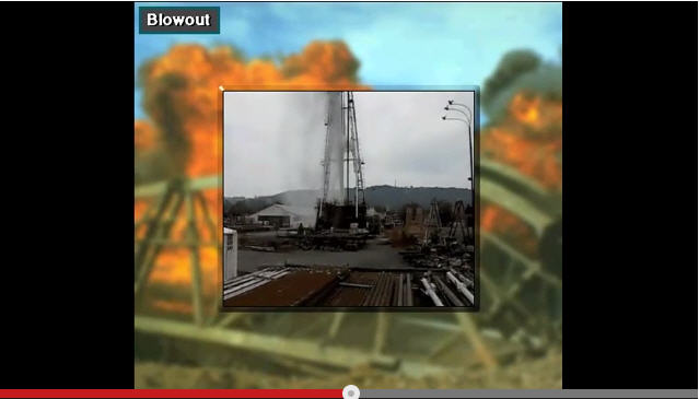
A blowout is dangerous. Formation fluids like gas and oil rise to the surface and burn. Blowouts can injure or kill destroy the rigs or the environment. Rig crews therefore train and work hard to prevent blowouts. Usually they are successful, so blow outs are rare but when they happen they spectacular and thus often make the news.
A kick is the entry of formation fluids into the well bore while drilling. Kick occurs when the pressure exerted by the drilling mud is less than the pressure in the formation of the drill string is penetrating. The mud that circulates down the drill string and up the hole is the first line of defense against kicks. Drilling mud creates additional pressure as it circulates. The mud pressure keeps the formation pressure from entering the well bore. On the rig, it is said that the mud keeps the well from kicking.
Sometimes however crew members may accidentally allow the mud level or the weight in the hole to drop. This drop in weight or level can happen for several reasons. For example the crew may fail to keep the hole full of mud, may pull the pipe out of it or they may pull the pipe tool fast which can lower the bottom hole in pressure. When the mud level or at the mud weight drops the pressure exerted on the formation decreases. If either happens formation fluids can enter the hole. If they do the well takes a “kick.”
In other words when the formation weight exceeds the pressure of the mud column then the well can kick. To keep a kick from becoming a blowout the rig crew uses blowout prevention equipment.

API Ring Gaskets Used in BOP Connections

$
0
0

There are several API types of ring gaskets used in BOP connections and this is very important to personnel involving in drilling operation to know about it. API 6A: Specification for Wellhead and Christmas Tree Equipment is the standard which every manufacture refers to their equipment.

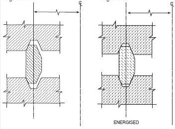
API Type R Ring Gasket

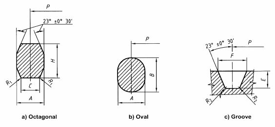
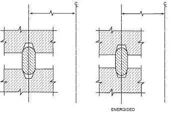
The API type “R” rig gasket is not a pressure energized gasket therefore this type does NOT recommend for BOP equipment or safety critical equipment as x-mas tree, wellhead valves, etc. Sealing area is along small bands of contact between the gasket and the ring gasket on both ID and OD of the gasket. Shape of type “R” may be oval or octagonal in cross section (see Figure 1). Additionally, face to face between flanges will not touch when the flanges are tightened (see Figure 2). The “R” gasket is compatible for 6B flanges.

 Figure 1 - Type R ring gaskets (shape and groove)


Figure 1 - Type R ring gaskets (shape and groove)

Figure 2 - Type R Gasket When Energized

Figure 2 - Type “R” Gasket When Energized

API Type “RX” Ring Gasket

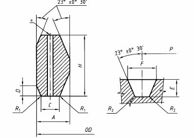
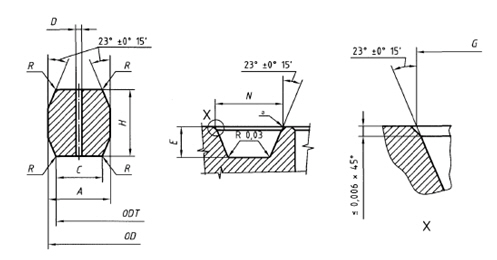
RX ring gasket is a pressure energized ring joint gasket and sealing area when energized is along small bands of contact between the groove and the OD of the ring gasket (see Figure 3). This gasket is manufactured a little bit bigger in diameter than the ring groove therefore when it is compressed, it will deform and seal the pressure. The “RX” is also not a face to face contact (see Figure 4). This gasket must be utilized only one time. The “RX” gasket is compatible for 6BX flanges and 16B hubs.

 Figure 3 - Type RX Ring Gasket (Shape and Groove)

Figure 3 - Type RX Ring Gasket (Shape and Groove)

Figure 4 - Type RX Gasket When Energized

Figure 4 - Type “RX” Gasket When Energized

API Face-to-Face Type “RX” Ring Gasket

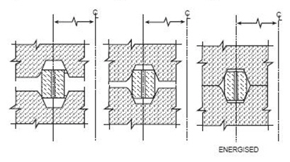
The face-to-face “RX” ring gasket is similar to “RX” gasket except it has increased groove width to ensure face to face contact between flanges or hubs (see Figure 5). However, this leaves the gasket unsupported on its ID. It is pressure-energized gasket which was adopted by API. This gasket may not remain in a perfect round shape when it is tightened because it does not have the support from ID of the ring groove.

 Figure 5 - Face-to-Face Type RX Ring Gasket

Figure 5 – Face-to-Face Type “RX” Ring Gasket

API Type “BX” Ring Gasket

API Type “BX” (Figure 6) is a pressure energized ring and it is designed for face-to-face contact between hubs or flanges. When energized, small contact bands between OD of the ring gasket and the rig groove is the sealing area. This ring gasket is slightly bigger than the ring groove. Therefore, when the hubs or flanges are tightened, the gasket will be slightly compressed into the rig groove to seal pressure (see Figure 7). Since this is face-to-face contact type, the tolerance of the gasket and ring groove is vital. If you have the gasket at the high side of tolerance and the groove at the low side of tolerance, it will be quite difficult to achieve face-to-face contact. The “BX” gasket is compatible for 6BX flanges and 16BX hubs.

Figure 6 - API Type BX Ring Gasket

Figure 6 - API Type “BX” Ring Gasket

 Figure 7 - API Type BX Ring Gasket When Energized

Figure 7 – API Type “BX” Ring Gasket When Energized

 Reference book: Well Control Books

Why Do We Need To Minimize Influx (Kick)?

$
0
0

As you know, we’ve always been trained or told to minimize influx (kick). Nowadays, there are several tools and procedures guiding us to prevent large influx; however, interestingly there are quite a lot of people who don’t understand why we need to do this. In this topic, we will demonstrate how kick volume will affect wellbore and surface casing pressure.

Why-Do-We-Need-To-Minimize-Influx-(Kick)

Main concept of minimizing kick coming into the wellbore is to minimize surface casing pressure when shut in. If you have excessive surface casing pressure, you will have a chance to fracture the weakest formation in the wellbore such as formation at casing shoe. You need to remember that more influx equals to more surface pressure. We will do basic calculation to see the effect of kick volume and surface pressure.

Example: Use the following information and compare the result of 2 cases.

Well Information (figure 1)

Figure 1 - well info

Figure 1 - Well Information

  • 9-5/8” casing shoe was set at 5,000’MD/5,000’TVD.
  • The well is drilled to 10,000’MD/10,000’TVD with 8.5 bit.
  • The well is assumed to be a gauge hole.
  • Current mud weight is 9.2 ppg water based mud.
  • Leak off test performed at 9-5/8” casing shoe is 13.5 ppg equivalent.
  • Reservoir pressure at 10,000’ TVD is 10.5 ppg equivalent.
  • Average gas gradient is 0.1 psi/ft.
  • 5” DP is used to drill this section and 6-1/2” DC is used as BHA for 1,000 ft.

What will happen if the wellbore influx is 10 bbl and 50 bbl?

First of all, we need to determine influx height of 10 bbl and 50 bbl.

Influx Height = Kick Volume ÷ Annular Capacity

Annular Capacity between 8-1/2” hole and 5” DP = (8.52 – 52) ÷ 1029.4 = 0.04590 bbl/ft

Annular Capacity between 8-1/2” hole and 6.5” DC = (8.52 – 6.52) ÷ 1029.4 = 0.02194 bbl/ft

Height of 10 bbl

Influx Height @ 10 bbl = 10 ÷ 0.02194 = 343 ft

 Figure 2 - Height of 10 bbl kick

Figure 2 – Height of 10 bbl kick

Height of 50 bbl

For this case, we need to check see if 50 bbl will be more than annular volume between hole and drill collar.

Volume between hole and 6.5” DC = Annular Capacity x DC Length

Volume between hole and 6.5” DC = 0.02914 x 1,000 = 29.14 bbl

As you can see from the figure, it tells us that there is kick volume in the annulus between hole and 5” DP.

Kick Volume between Hole and 6.5” DC = Total Kick Volume – Volume between hole and 6.5” DC

Kick Volume between Hole and 6.5” DC = 50 – 29.14 = 20.86 bbl

We know that we will have 20.86 bbl of kick between hole and 5” DP and then we need to calculate height of that volume.

Influx Height @ 20.86 bbl = 20.86 ÷ 0.04590 = 454 ft

Total Influx Height = Influx Height between DC and Hole + Influx Height between DP and Hole

Total Influx Height = 1000 + 454 = 1454 ft

 Figure 3 - Height of 50 bbl kick

Figure 3 – Height of 50 bbl kick

What is formation pressure at 10,000’MD/10,000TVD?

Formation pressure = 0.052 x 10.5 x 10,000 = 5,460 psi

What is Maximum Initial Shut-in Casing Pressure (MISICP)?

Maximum Initial Shut-in Casing Pressure (MISICP) = (LOT – Current MW) x 0.052 x Shoe TVD

Maximum Initial Shut-in Casing Pressure (MISICP) = (13.5 – 9.2) x 0.052 x 5,000 = 1,118 psi

Then we need to apply the hydrostatic pressure concept to determine casing pressure as per the relationship below.

Formation Pressure = Hydrostatic Pressure + Casing Pressure

Re-write to the equation below

Casing Pressure = Formation Pressure – Hydrostatic Pressure

Hydrostatic Pressure with 10 bbl of Kick in The Well

Hydrostatic Pressure = Hydrostatic from Gas + Hydrostatic from Mud

Hydrostatic Pressure = (Gas Gradient x Height of Gas) + (0.052 x MW X Height of Mud)

Hydrostatic Pressure = (0.1 x 343) + (0.052 x 9.2 x (10,000 – 343)) = 4,654 psi

Casing Pressure with 10 bbl of Kick in The Well

Casing Pressure = 5,460 – 4,654 = 806 psi (Figure 4)

Figure 4 - Casing Pressure with 10 bbl gas kick

Figure 4 – Casing Pressure with 10 bbl gas kick

Hydrostatic Pressure with 50 bbl of Kick in The Well

Hydrostatic Pressure = Hydrostatic from Gas + Hydrostatic from Mud

Hydrostatic Pressure = (Gas Gradient x Height of Gas) + (0.052 x MW X Height of Mud)

Hydrostatic Pressure = (0.1 x 1454) + (0.052 x 9.2 x (10,000 – 1545)) = 4,233 psi

Casing Pressure = 5,460 – 4,233 = 1,227 psi (Figure 5)

Figure 5 - Casing Pressure with 50 bbl gas kick

 Figure 5 - Casing Pressure with 50 bbl gas kick

Based on the same assumption, we will get the surface pressure as listed below

Casing Pressure with 10 bbl kick = 806 psi

Casing Pressure with 50 bbl kick = 1,227 psi

If we compare with MISICP of 1,118 psi from the calculation above, we will see that 50 bbl kick will break the casing shoe (Figure 6).

Figure 6 - Shoe Fracture

Figure 6 - Shoe Fracture

Conclusion

More Kick = More Surface Pressure = Less Safe

Less Kick = Less Surface Pressure = Safer

 Reference book: Well Control Books

Basic Blow Out Preventer – VDO Training

$
0
0

Blow Out Preventer is one of the most critical equipment on the rig therefore it is very important that you need to understand it. This VDO demonstrates the basic of BOP with a lot of colorful pictures which will help you learn about it. We also add full VDO transcript in order to help people fully understand this topic. We wish you would love this.

Full VDO Transcript Deails

BOP-basic-fb

The blowout preventer, BOP stack, consists of several large valves stacked on top of each other. These large valves are called blowout preventers. Manufacturers rate BOP stacks to work against pressures as low as 2m000 pounds per square inch or psi and as high as 15,000 psi. That is about 14,000 kPa to over 100,000 kPa.

Rigs usually have two kinds of preventers, on top is an annular preventer it is called an annular preventer because it surrounds the top of the well bore in the shape of a ring or an annulus. Below the annular preventer are ram preventers. The shutoff valves in RAM preventers close my forcing or ramming themselves together.

The choke line is a line through which well fluids flow through the choke manifold when the preventers are closed. Even though the preventers shut in the well the core members must have a way to remove or circulate the kick in the mud out of the well. When the BOP shut in the well, mud and formation fluids exit through the choke line to the choke manifold. The manifold is made up of special piping and valves. The most important valve is the choke.

The choke is a valve that has an adjustable opening. Crew members circulate the kicks to the choke to keep back pressure on the well. Keeping the right amount of back pressure prevents more tick fluids from entering the well. At the same time they can get the kick out of the well and putting heavier mud to kill the well, that is, regain control of it. The well fluids leave the choke manifold and usually go to a mud-gas separator.

A mud-gas separator separates the mud from the gas in the kick. The clean mud goes back to the tanks, the gas is flared or burn a safe distance away. When the well takes a kick and the BOPs are open, well fluids force mud to flow the well bore and into the BOP stack. When the driller closes the annular BOP, flow stops. Usually drillers close the annular BOP first. The closed annular BOP diverts the flow of the choke like which goes to the choke manifold. The driller can open a line on the choke line and safely circulate the kick through the choke manifold.


Buoyancy Factor Table Free Download

$
0
0

Buoyancy factor is the factor that is used to compensate loss of weight due to immersion in drilling fluid and you can find the calculation from here http://www.drillingformulas.com/buoyancy-factor-calculation/.

bf-table-facbook

We have created a simple table to help people determine the buoyancy factor quickly. Let’s take a look at the table. In Figure 1, it shows the main page and you can select the mud weight range from 4.0 ppg to 19.0 ppg.

 Figure 1- Main Page BF Table

Figure 1- Main Page BF Table

For instant, we choose 8.0 ppg and the table will show buoyancy from 8.0 – 8.9 ppg (Figure 2)

Figure 2 - Buoyancy Factor for 8 ppg Range

Figure 2 – Buoyancy Factor for 8 ppg Range

 The table shows the buoyancy factor from mud weight range from 8.0 – 8.9 ppg. Additionally, the table demonstrates mud weight in kg/l. For example, if we select 8.5 ppg, the table will tell you the buoyancy factor of 0.8702 (Figure 3).

 Figure 3 - 8.5 ppg and Buoyancy Factor

Figure 3 - 8.5 ppg and Buoyancy Factor


If you want to go back to the main page, you just simply click “Go Back To Main Page”.

 Figure 4- Go Back to Main Page BF Table

Figure 4 - Go Back to Main Page BF Table

 Download the Buoyancy Factor Table from this link => Excel-icon-40-40  http://goo.gl/AIzMeS

If you think this is good for your friends, please feel free to share with them.


How To Free Stuck Pipe (Oilfield)

$
0
0

This article is a summary of how to free stuck pipe caused by three main mechanisms which are wellbore geometry, differential sticking and packing/bridging off. It will give you some ideas which you can apply for your operation.

How-to-free-a-stuck-pipe

Free Stuck Pipe Caused By Wellbore Geometry

These following instructions are guide lines on how to free the stuck drill string caused by wellbore geometry.

What should you  do to free the stuck pipe caused by wellbore geometry ?

• If the drill string gets stuck while moving up, jar down with maximum trip load and torque can be applied into drill string while jarring down. Be caution while applying torque, do not exceed make up torque.

• On the other hand, if the drill string gets stuck while moving down, jar up with maximum trip load. DO NOT apply torque in the drill string while jarring up.

• Flow rate must be reduced while attempting to free the drill string. Do not use high flow rate because it will make the stuck situation became worse and you will not be able to free the pipe forever.

• To free the string, jarring operation may take long time so please be patient.

• If a formation you get stuck is limestone or chalk, acid can be spotted to dissolve cuttings around the pipe.

• If the drill string is stuck in a salt formation, spotting fresh water is another choice to clear the salt in the annulus.

• Please always seriously consider regarding well control prior to spotting light weight stuff (acid or fresh water) around the drill string. You must ensure that you are still over balance formation pressure otherwise you will be dealing with well control too.

What should you  do after the string becomes free?

• Increase flow rate and circulate to clean wellbore. Flow rate must be more than cutting slip velocity in order to transport cuttings effectively.

• Reciprocate and work pipe while cleaning the hole.

• Ensure that the wellbore is clean prior to continuing the operation.

• Back ream or make a short trip the section that causes the problem.


Free Stuck Pipe Caused By Differential Sticking

These following instructions are guide lines on how to free the stuck drill string caused by differential sticking.

• Apply maximum flow rate as much as you can.

• Apply maximum torque in the drillstring and work down torque to stuck depth. Torque in the string will improve chance of free the pipe.

• Slack off weight of string to maximum sit down weight.

• Jar down with maximum trip load. Torque may be applied with jarring down with caution. The chance of freeing the pipe by jarring down is more than jarring up. Please be patient when a hydraulic jar trips because it may take around 5 minutes each circle.

The secondary actions to free the pipe that you may try

• Reduce hydrostatic pressure by pumping low weight mud/pill. You must ensure that overall hydrostatic pressure is still able to control reservoir fluid to accidentally come into the wellbore.

• Continue jarring down with maximum trip load and apply torque into drill string.

• It may take long time to free the pipe therefore personnel must be patient.

What should you  do after the string becomes free?

• Circulate at maximum allowable flow rate. Flow rate must be more than cutting slip velocity in order to transport cuttings effectively.

• Reciprocate and work pipe while cleaning the hole. Ensure that you can work pipe with full stand or joint while circulating.

• Condition mud prior to drilling ahead because if you still drill with poor mud properties, the differential sticking will be re-occurred.


Free Stuck Pipe Caused by Pack off / Bridging


These following instructions are guide lines on how to free the stuck drill string  cause by packing off or bridging off.

What should you  do to free the stuck pipe caused by Pack off / Bridging?

• Circulate with low flow rate (300 – 400 psi pumping pressure). This is very important to apply low flow rate because if high flow rate is applied, the stuck situation becomes worse.

• If the drill string gets stuck while moving up or with the string in static condition, jar down with maximum trip load and torque can be applied into drill string while jarring down. DO NOT JAR UP. Be caution while applying torque, do not exceed make up torque.

• On the other hand, if the drill string gets stuck while moving down, jar up with maximum trip load. DO NOT apply torque in the drill string while jarring up.

• To free the string, jarring operation may take long time (10 hours +) so please be patient.

What should you do after the string becomes free?

• Increase flow rate and circulate to clean wellbore at maximum allowable flow rate. Flow rate must be more than cutting slip velocity in order to transport cuttings effectively.

• Reciprocate and rotate while circulating to improve hole cleaning ability. Work the drill string with full stand if possible.

• Ensure that the wellbore is clean prior to continuing the operation. You can see from the sale shaker whether the hole is clean or not.

• Sweep may be utilized to improve hole cleaing.

• Back ream or make a short trip through the area where causes the stuck pipe issue.

What is the last option to free the stuck pipe if you have tried several ways already??

You may need to pray: )

New-Method-to-free-stuck-pipe

Increase In Mud Weight Due To Cutting

$
0
0

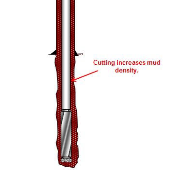
Cutting generated while drilling will increase drilling fluid density and it will finally affect equivalent circulating density while drilling. In this topic, we will talk about how to determine mud weight increase due to cutting.

 Figure 1 - Cutting Increases Mud Density

Figure 1 – Cutting Increases Mud Density


Effective mud density due to cuttings in the hole can be determined by the empirical equation below;

euqation pm

Where;

ρeff is effective mud density in ppg.

ρm is mud density in ppg.

Q is flow rate in gpm.

ROP is rate of penetration in fph.

db is wellbore diameter or bit diameter in inch.

The effective mud density is the combination of drilling mud density and cutting density. We can write in term of equation below.

ρeff = ρm + ρc — Equation 2

Equivalent Circulating Density (ECD) consists of three components given by the equation below;

ECD = ρm + ρc + ρa — Equation 3

Where;

ρeff is effective mud density in ppg.

ρm is mud density in ppg.

ρc is cutting density in ppg.

ρa is annular pressure loss in ppg.

As you can see from the equation 1 and 3, the more the well is drilled, the more effective mud density which will increase ECD of the well.

Example: The well was drilled with 12-1/4” bit and the average ROP is 150 fph. Flow rate while drilling is 900 gpm and the rig was using 9.2 ppg mud (Figure 2). Determine the effective mud density from the information.

Figure 2 - Drilling information

Figure 2 - Drilling information

 The parameters given are listed below;

ρm = 9.2 ppg

Q = 900 gpm

ROP = 150 pfh

db = 12.25 inch

Using the equation#1, we will get the effective mud density.

euqation pm2 with figure

ρeff = 9.39 ppg

The effective mud density is 9.39 ppg. It means that you will have 2% increase in mud weight due to cutting with these drilling parameters.

Reference book => formulas-and-calculationFormulas and Calculations for Drilling Operations 

Maximum ROP Before Fracture Formation

$
0
0

In this topic, we will apply the effective mud density formula to determine maximum ROP before fracturing formation.

Figure 1 - Max ROP before Fracturing FormationFigure 1 – Max ROP before Fracturing Formation


These two equations that will be used to determine the maximum ROP are listed below;

Effective mud density due to cuttings in the hole can be determined by the empirical equation below;

equation 1

Where;

ρeff is effective mud density in ppg.

ρm is mud density in ppg.

Q is flow rate in gpm.

ROP is rate of penetration in fph.

db is wellbore diameter or bit diameter in inch.

 Equivalent Circulating Density (ECD) consists of three components given by the equation below;

Equivalent Circulating Density (ECD) = ρm + ρc + ρa — Equation 2

Where;

ρm is mud density in ppg.

ρc is cutting density in ppg.

ρa is annular pressure loss in ppg.

How To Apply These Two Concepts

Formation will be fractured if the ECD while drilling is more than fracture gradient. Additionally, besides mud weight (ρm), cutting density and annular pressure loss due to hydraulic contributes to ECD.

The ECD can be described in term of effective density and annular pressure as listed below;

Equivalent Circulating Density (ECD) = ρm + ρc + ρa — Equation 2

ρeff  = ρm + ρc — Equation 3

Equivalent Circulating Density (ECD) = ρeff + ρ — Equation 4

Equivalent Circulating Density (ECD) = Fracture Gradient (FG) — Equation 5

With those relationships above, we can derive the maximum ROP into the following formulas.

quation 6

Example – Determine the maximum ROP for this well.

Figure 2 - Well Information

Figure 2 – Well Information

Leak off test at shoe is 12.5 ppg.

The well was drilled to 9,500’MD/9,500’TVD

Mud weight is 10.5 ppg.

Annular pressure loss is 600 psi.

Flow rate is 800 gpm.

Hole size is 12.25”.

Solution

ECD should not exceed the leak off test value; therefore ECD is equal to 12.5 ppg.

Annular pressure loss (ρa) = 600 ÷ (0.052 x 9,500) = 1.21 ppg

quation -max rop result

Max ROP = 647.2 fph

Reference book => formulas-and-calculationFormulas and Calculations for Drilling Operations 

How Does Deep Water Drilling Work

$
0
0

Nowadays deep water drilling is one of vital players for oil and gas exploration and production industry and there are many people who would like to know how deep water drilling works. We’ve found one excellent VDO demonstrates the deep water drilling process in a simple way. This VDO will give you clearer picture about the topic and we also add full VDO transcript in order to help more people understand the content clearly. We wish you would enjoy learning from this VDO and please feel free to give us feedback : )

Full VDO Transcript - How Does Deep Water Drilling Work

deep-water-drilling

Credit: Image from Wikipeida

How does the deep sea drilling vessel Chikyu drill into the sea floor? When the vessel arrives at the drilling site it receives a satellite signal that helps the vessel moves into the exact position required. The vessel has six propellers that rotate a full 360 degrees and keep the vessel in one position preventing it from drifting due to the wind, waves or sea current.

First the conductor pipe is installed. As the drill pipes are connected, the conductor pipe and guide are run down to the sea floor. After the conductor pipe penetrates the sea floor the drill pipe is released and pulled back to the vessel. A large drill bit connected to the bottom of the drill pipe is run down to the sea floor. The drill bit is lead down to the bottom of the hole through the conductor pipe. The drill bit rotates and drills the sediment and rock below the sea bed. Sea water is sprayed from nuzzles on the drill bit to raise the cuttings to the sea floor.

After drilling several hundred meters the drill bit is pulled back to the vessel. A casing pipe about 50cm in diameter is set into the drill hole to keep it from collapsing. The casing pipe is run down through the conductor pipe and is inserted into the hole using the drill pipe.

Cement is pumped into the space between the hole and the casing pipe to fix the pipe in place. After cementing, the drill pipe is released and pulled back to the vessel. The Chikyu is equipped with a riser system in order to drill into the earth even deeper. As the riser pipes are added one after the other, the Blow Out Preventer is run down to the sea floor. The Blow out Preventer is connected to a well head which is located on top of the casing pipe. The vessel is now connected to the sea floor via the riser pipe.

A drill bit, smaller than the one first used is run down the through riser pipe and casing pipe. The drilling begins. Once the riser pipe has been connected, drilling mud is used instead of sea water. When the target depth is reached the drill bit is pulled back to the vessel. To drill the hole even deeper, a narrower casing pipe is sent to set in the drilled hole. After the casing pipe has been installed, cement is pumped into the space between the hole and the casing pipe to fix the pipe in place. Again, an even smaller drill bit is run down through the riser pipe and casing pipe and the drilling continues. Repeating this process, the Chikyu will drill through the ocean crust to collect fresh live mantle. This is something that has never been done before.

Rotary Drilling

Rotary Drilling is used for ocean drilling. Let’s look at the features of this method.

First the drill pipes are connected one after another as they run down to the sea floor. The work of connecting the drill pipes and drilling the hole are powered by a motor on the derrick. The drill pipe has a drill bit attached to the bottom. With rotary drilling, the drill pipe is rotated and the drill bit at the end crushes sediment and rock to make the hole. After a while, cuttings accumulate at the bottom and drilling cannot go any further. Sea water or other liquid is then pumped from the vessel down through the drill pipe and is jetted out of the nuzzles on the drill bit. This liquid current forces the cuttings up to the sea floor. That is Rotary Drilling.

Riser System

The deep sea drilling vessel Chikyu can drill over 7 kilometers below the sea floor into the earth. To drill even further before the sea floor. A riser system is used. With the riser system mud is used instead of sea water. There are several reasons for using mud. First it has greater viscosity than sea water to force cuttings from the bottom of a deeper hole. Also with the increase in pressure at the greater depths the formation pressure becomes much greater than the pressure in the hole filled with sea water. The hole will collapse if a certain differential pressure between the outside and the inside of the hole is reached. Mud has a higher density than water. Therefore the pressure inside the hole remains higher and the hole will not cave in allowing deeper drilling.

The drilling mud is artificially conditioned with various kinds of product and it is expensive. Discharging it on the sea floor is bad both environmentally and economically. The mud is therefore collected and reused. For this purpose the riser pipe is connected all the way from the vessel to the sea floor. The drilling mud sprayed out of the drill bit returns to the vessel through the riser pipe together with the cuttings and is collected and recycled at the vessel. Riser drilling not only makes it possible to drill deep into the earth; it is a break through drilling method that is environmentally and economically sound. Riser drilling will make it possible to drill all the way down into the earth’s mantle. A depth never before reached in all of history.


Viewing all 497 articles
Browse latest View live


<script src="https://jsc.adskeeper.com/r/s/rssing.com.1596347.js" async> </script>