Quantcast
Channel: Drilling Formulas and Drilling Calculations
Viewing all 497 articles
Browse latest View live

Buoyancy Factor with Two Different Fluid Weights in The Well

$
0
0

Buoyancy Factor is the factor that is used to compensate loss of weight due to immersion in drilling fluid and you can find more information from this article > buoyancy factor calculation .  In that article, it demonstrates the buoyancy formula only for one fluid in the wellbore. However, this time, we will have the details about buoyancy factor when inside and outside fluid are different.

Buoyancy factor with different fluid inside and outside of tubular is listed below;

equation 1

Where;

Ao is an external area of the component.

Ai is an internal area of the component.

ρo is fluid density in the annulus at the component depth in the wellbore.

ρi is fluid density in the component depth in the wellbore.

ρs is steel weight density. Steel density is 65.4 ppg.

If you can the same mud weight inside and outside, the equation 1 will be like this

equation 2

This is the same relationship as this article buoyancy factor calculation.

Let’s take a look at the following example to get more understanding.

Example

13-3/8” casing shoe was at 2,500’MD/2,000’TVD

9-5/8” casing was run to 6,800’MD/6,000 TVD.

9-5/8” casing weight is 40 ppf and casing ID is 8.835 inch.

Current mud weight is 9.5 ppg oil based mud.

The well bore diagram is show below (Figure 1).
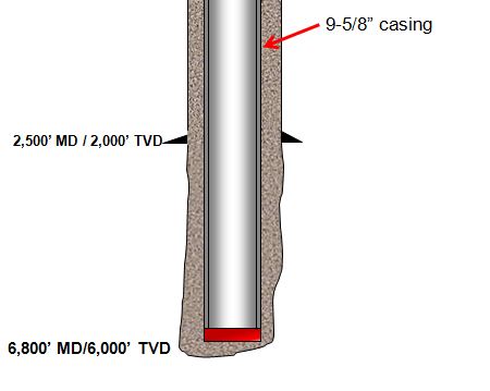
 Figure 1 - Wellbore Diagram

Figure 1 - Wellbore Diagram

The well is planned to cement from shoe to surface and the planned cement weight is 14.0 ppg. The displacement fluid is drilling mud currently used.

Please determine the following items.

  • Air weight of casing string
  • Buoyed weight of casing in drilling mud
  • Buoyed weight of casing when cement is inside casing and drilling mud is outside casing
  • Buoyed weight of casing when cement is outside casing and drilling mud is inside casing

Air weight of casing string

Air weight of casing string, lb = length of casing, ft x casing weight, lb/ft

Air weight of casing string, lb = 6,800x 40 = 272,000 lb

Buoyed weight of casing in drilling mud

 Figure 2 - Bouyed Weight When Submersed In Drilling Mud

Figure 2 - Buoyed Weight When Submersed In Drilling Mud

Buoyed weight = Buoyancy Factor (BF) X Air Weight of Casing

equation 2.5

Buoyancy Factor (BF) = 0.855

Buoyed weight = 0.855 X 272,000 = 232,489 lb

Buoyed weight of casing when cement is inside casing and drilling mud is outside casing

 Figure 3 - Buoyed weight of casing when cement is inside casing and drilling mud is outside casing

Figure 3 - Buoyed weight of casing when cement is inside casing and drilling mud is outside casing

 We will apply the Equation-1 for this case.

Ao is an external area of the component.

Ao = π x (Outside Diameter of casing)2 ÷ 4

Ao = π x (9.625)2 ÷ 4 = 72.76 square inch

Ai is an internal area of the component.

Ai = π x (Inside Diameter of casing)2 ÷ 4

Ai = π x (8.835)2 ÷ 4 = 61.31 square inch

ρo = 9.5 ppf (mud in the annulus)

ρi = 14.0 ppg (cement inside casing)

ρs = 65.4 ppg.
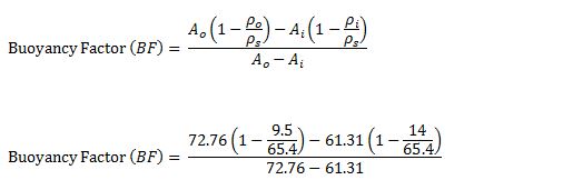
equation 3

Buoyancy Factor (BF) = 1.22

Buoyed weight = 1.22 X 272,000 = 331,840 lb


Buoyed weight of casing when cement is outside casing and drilling mud is inside casing

 Figure 4 - Buoyed weight of casing when cement is outside casing and drilling mud is inside casing

Figure 4 - Buoyed weight of casing when cement is outside casing and drilling mud is inside casing

We will apply Equation-1 for this case as well.

All the calculation parameters are the same.

Ao = π x (9.625)2 ÷ 4 = 72.76 square inch

Ai = π x (8.835)2 ÷ 4 = 61.31 square inch

ρo = 9.5 ppf (mud in the annulus)

ρi = 14.0 ppg (cement inside casing)

ρs = 65.4 ppg.

equation 4


Buoyancy Factor (BF) = 0.42

Buoyed weight = 0.42 X 272,000 = 114,240 lb

Conclusion: At different stage of the well, you may have different buoyed weight depending on density of fluid inside and outside of the component and it is not always that buoyed weight is less than air weight.

Reference book => formulas-and-calculationFormulas and Calculations for Drilling Operations 

Halliburton Red eBook App – It is a Useful App for Oilfield Personnel

$
0
0

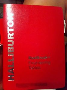
The Halliburton Redbook (Figure 1) is a very useful for oilfield people because it contains a lot of useful information as tubular/drill pipe data, cementing information, some oilfield calculation, etc.

Halliburton Red Book

Figure 1 – Halliburton Red Book

Nowadays, you can have another option to have this book by installing the Halliburton eRedBook® Mobile (Figure 2) in your smart phone or tablet.  It will make your life a lot easier.

 Halliburton eRedBook

Figure 2 – Halliburton eRedBook® Mobile


What can Halliburton eRedBook® Mobile help you?

There are four main parts (Figure 3) which are Dimension & Strengths, Tub/Cas/Pipe in Hole, Tub/Cas/Pipe in Casing and Capacity.

 figure-3-4-main-part-in-the-app

Figure 3 – Main parts of this app

Dimension and Strength

In this part, you can get the dimension and strength of casing, tubing, drill pipe and coil tubing.  For instance, you can input information required for casing as OD, weight, ID and grade (Figure 4) and you will get the technical detail of pipe you need (Figure 5).

figure-4-dimension-and-strengths

Figure 4 – Input Casing Information

figure-5-result

Figure 5 – Technical Information

Tub/Cas/Pipe in Hole

This section will give you volume and capacity between pipe and hole (Figure 6 and Figure 7) and you can also add % excess into the system as well.

Figure-6-TubCasPipe in Hole

Figure 6 – Tub/Cas/Pipe in Hole

Figure-7-TubCasPipe in HoleResult

Figure 7 – Tub/Cas/Pipe in Hole Result

Tub/Cas/Pipe in Casing

This section, Tub/Cas/Pipe in Casing, (Figure 8) will give you annular volume and annular capacity based on casing depth, inner OD and outer ID of assigned tubular (Figure 9 and Figure 10).

 Figure-8-TubCasPipe in Casing

Figure 8 – Tub/Cas/Pipe in Casing

 Figure-9-TubCasPipe in Casing-input

Figure 9 – Tub/Cas/Pipe in Casing Input

Figure-10-TubCasPipe in Casing-result

Figure 10 – Tub/Cas/Pipe in Casing Result

Capacity

This section (Figure 11) will determine capacity of tubular. You input information required (Figure 12) and the app will show you results (volume and capacity) in several units (Figure 13).

Figure-11-capacity

Figure 11 – Capacity

Figure-12-capacity-inpput

Figure 12 – Input Information To Determine Capacity

 Figure-13-capacity-result

Figure 13 – Results of Capacity

Options

The Halliburton eRedBook® Mobile also allows uses to configure several options (Figure 14) such as unit of measurement, configure results, etc.


Figure-13-Unit

Figure 14 – Options

Conclusion: This application is specially made for oilfield workers. You can find the information less than a minute and the app will also accurately calculate some important figures for you. Additionally, it is totally FREE. This is highly recommended.

Where to Download

The application is available in IOS and Android system and the following links are the download links.

IOS - https://itunes.apple.com/th/app/halliburton-eredbook-mobile/id507496941?mt=8

Andriod - https://play.google.com/store/apps/details?id=com.halliburton.corp.eredbook&hl=en

We wish this post would be advantageous for you and please feel free to share with your friends.

Volume of Cutting Generated While Drilling

$
0
0

While drilling, cuttings are generated every footage drilled and this topic will demonstrate how to determine volume of cutting entering into the wellbore.

Figure 1 - Cutting Generated While Drilling

Figure 1 - Cutting Generated While Drilling

 The following formula is used to calculate cutting volume generated while drilling;

vc - bbl per hour

Where;

Vc is volume of cutting in bbl/hr.

Ø is formation porosity (%).

D is wellbore diameter in inch.

ROP is rate of penetration in feet per hour.

Vc can be presented in several unit as follows;

Vc in gallon per hour is shown below;

vc - gallon per hour

Vc in gallon per minute is shown below;

vc - gallon per minute

Example: Determine volume of cutting in gallon per hour entering into the well bases on the following information.

Well depth 9,500’ MD/8,000’ TVD.

Average ROP = 80 fph

Average formation porosity = 20 %

Bit size = 8-1/2”

Assume gauge hole

Figure 2 - Well and Drilling Information

Figure 2 - Well and Drilling Information


Vc in gallon per hour is shown below;

vc - gallon per hour (example)

Vc = 188.8 gallon/hr

This figure tells you that with the drilling parameter, you must be able to remove the cutting faster than what you generate in order to eliminate operation issues as stuck pipe.

Reference book => formulas-and-calculationFormulas and Calculations for Drilling Operations 

Shale Gas Rig On Fire

$
0
0

This is information which I got from my friends and I would like to share with you in order to emphasize the important of well control. I am not sure about the rig name. See photos and details below;


On Tuesday at around 4:16 pm local time, there has been an explosion and fire at Nabors Drilling Rig owned that worked for Whiting Petroleum, in the state of McKenzie, North Dakota. At that time a new rig drill depth of 15,000 feet, then there is pressure from the kick in the hole with a material that causes bursts of fire. Fire Brigade was spraying foam to extinguish it. A worker named Brian Busby suffered burns on his hands and his head and was rushed to the General Hospital in the town of Watford McKenzie to get treatment.

Source: Facebook.com

Well control is very important so we would like you to learn some well control information from our website and we also provide well control quiz for free.


Basic Understanding of Hydraulic Fracturing

$
0
0

Geologists have known for years that substantial deposits of oil and natural gas are trapped in deep shale formations. These shale reservoirs were created tens of millions of years ago. Around the world today with modern and horizontal drilling techniques and hydraulic fracturing, the trapped oil and natural gas in these shale reservoirs is being safely and efficiently produced, gathered and distributed to customers.

basic-understanding-of-hydraulic-fracturing

Let’s look at a drilling and completion process of a typical oil and natural gas well. Shale reservoirs are usually one mile or more below the surface.  Well below any underground source of drinking water, which is typically no more than 300-1000 feet below the surface(Figure 1)

Figure 1 - Reservoir Formation

Figure 1 – Reservoir Formation

Additionally, steel pipes called ‘casing’ cemented in place, provide a multilayered barrier to protect fresh water aquifers. During the past 60 years, the oil and gas industry has conducted fracture stimulations in over 1 million wells worldwide.

The initial steps are the same as for any conventional well; A hole is drilled straight down using fresh water based fluids which cools the drill bit, carries the rock cuttings back to the surface and stabilizes the wall of the well bore. Once the hole extends below the deepest fresh water aquifer the drill pipe is removed and replace with steel pipe called ‘surface casing’.

Next cement is pumped down the casing. When it reaches the bottom it is pumped down and then back up between the casing and the bore hole wall  creating an impermeable additional protective barrier between the well bore and any fresh water sources (Figure 2).

 Figure 2 - Surface Casing

Figure 2 – Surface Casing

In some cases depending on the geology of the area in the depth of the well, additional casing sections may be run and like surface casing, are then cemented in place to ensure no movement of fluid or gas between those layers and the ground water sources.

What makes drilling for hydrocarbons in a shale formation unique is the necessity to drill horizontally. Vertical drilling continues to a depth called the ‘kick off point’. This is where the well bore begins curving to become horizontal. One of the advantages of horizontal is that it is possible to drill several wells from one service drilling pad, minimizing the impact to the surface environment (Figure 3).

 Figure 3 - Horizontal Drilling

Figure 3 – Horizontal Drilling

When the targeted distance is reached, the drill pipe is removed and an additional steel casing is inserted through the full length of the well bore. Once again, the casing is cemented in place. For some horizontal developments, new technology in the form of sliding sleeves and mechanical isolation devices, replace the creation of isolation will what’s the drilling is cement in the creation of isolations along the well bore. Once the drilling is finished and the final casing has been installed, the drilling rig is removed and preparations are made for the next steps: well completion.

The first step in completing a well, is the creation of a connection between the final casing and the reservoir rock. This consists of lowering a specialized tool called the perforating gun, which is equipped with shaped explosive charges down to the rock layer containing oil or natural gas. This perforating gun is then fired, which creates holes through the casing, cement, and into the target rock. These perforating holes connect to the reservoir and the wellbore. Since these perforations are only a few inches long, and are performed more than a mile underground, the entire process is imperceptible on the surface.

The perforation gun is then removed and in preparation for the next step: hydraulic fracturing. The process consists of bumping a mixture of mostly water and sand plus a few chemicals under controlled conditions into deep underground reservoir formations. The chemicals are generally for lubrication to keep bacteria from forming and help carry the sand. These chemicals typically range in concentrations from 0.1 to 0.5% by volume, and help to improve the performance of the stimulation. This stimulation fluid is sent to trucks that pumped the fluid into the wellbore and out through the perforations that were noted earlier.

This process creates fractures in the oil and gas reservoir rock. The sand in the Frack fluid remains in these fractures in the rock and keep them open when the pump pressure is relieved. This allows the previously trapped oil or natural gas to flow to the wellbore more easily. This initial stimulation segment is it then isolated with a specially designed plug and a perforating guns are used to perforate the next stage. This stage is then hydraulically fractured in the same manner. This process is repeated along the entire horizontal section of the well which can extend several miles. Once this stimulation is complete, the isolation plugs are drilled out and production begins. Initially water and then the natural gas or oil, flows into the horizontal casing and up the wellbore. In in the course of the well as fluid as the course of initial production of the well, approximately 15 to 50% of the fracturing fluid is recovered. This fluid is either recycled to be used on other fracturing operations or safely disposed of according to government regulations (Figure 4).

Figure 4 - Well Stimulation (Fracking)

Figure 4 – Well Stimulation (Fracking)

The whole process of developing a well typically takes from 3 to 5 months. A few weeks to prepare the site, 4 to 6 weeks to drill the well and 1 to 3 months of completion activities, which includes 1 to 7 days of stimulation. But this 3 to 5 month investment can result in a well that will produce oil or natural gas for 20 to 40 years or more. When all of the oil or natural gas that can be recovered economically from a reservoir has been produced, work begins to return the land to the way it was before the drilling operations commenced. Wells will be filled with cement and pipes cut off 3 to 6 feet below ground level. All surface equipment will be removed and all pads will be filled in with dirt or replanted. The land can then be used again by the land owner for other activities and there will be virtually no visual signs that a well was once there. Today, hydraulic fracturing has become an increasingly important technique for producing oil and natural gas in places where the hydrocarbons were previously inaccessible. Technology will continue to be developed to improve the safe and economic development of oil and gas resources.

Basic Understanding of Sub Sea BOP VDO Training

$
0
0

Sub Sea BOP is one of the most critical well control equipment in deep water drilling and it is a good topic for everybody working on the rig to learn.

Sub-sea-BOP-equipment-fb-size

Today, we would like to share a valuable VDO training regarding the basic of sub sea BOP. Additionally, we provides learner full VDO transcript to accelerate your learning curve.

Basic Understanding of Sub Sea BOP VDO Transcript

Subsea BOP equipment is similar to a surface stack. There are however some very important differences. This section discusses these differences.

Subsea stacks attached to the well head on the seafloor meanwhile the rig floats on the water hundreds of thousands of feet or meters above. Major parts include;

BOP stack – this is a lot like a surface BOP stack. Other parts are different however, here is the flexible, or ball joint the marine riser with the choke line and kill line, guidelines, the telescopic joint with riser tensioners, the hose bundle and two control pods.

The generic controls the subsea BOP valves from an electric BOP control panel on the rig. This subsea hose bundle carries control signals and the hydraulic fluid from the rig down to the control pod and selected subsea BOP valves.

Marine riser pipe with special pipes and fittings.

It fills from the top of the subsea BOP stack and the drilling equipment located on the floating rig. Crew members run the drill string into the hole inside the riser pipe. The riser pipe also conducts drilling fluid up to the rig. Manufactures attach two smaller pipes called the choke and kill lines to the outside. Crewmembers use them to control the well during a kick or special operations.

Guidelines guide and help position equipment such as the BOP stack to ocean floor. The flexible joint cuts down on bending stresses from the riser pipe and BOP. The telescopic joint compensates for the vertical motion of the floating rig. Crewmembers also attach the riser tensioning system to it.

Riser tensioner lines support the riser pipe. The riser and guideline tensioners put constant tension on the riser pipe and guidelines. This tension suspends the riser pipe. It also compensates for the movement of the rig caused by wave action. Riser tensioning systems usually range in capacity to over 300,000 to almost 1,000,000 pounds and 135,000 to 455,000 kg with 50 feet or 50 m of wire line travel. They utilize up to 12 compression loaded tensioners that use air pressure for compensation.


Coring Cost Per Footage Drilled

$
0
0

Coring is a special process to recover wellbore rock in the well.

Figure 1 - Core from the well. Credit – Wikipedia
Figure 1 - Core from the well. Credit – Wikipedia

This article will demonstrate how to calculate coring cost per footage recovered.

coring-cost-per-foogate-drilled

 Coring cost per footage recovered is expressed below;

coring cost per foot formula

Where;

Cc = coring cost per foot

Cb = cost of core bit

Cs = cost of coring service from a service company

Cr = rig day rate

tt = trip time, hour

tc = core recovering time, hour

trc = core barrel handling time, hour

L = length of core recovered, ft

Rc = percentage of core recover, %

Example – Geologist plans to do coring from 14,000 – 14,500 ft. The information for this operation is listed below;

Coring bit = 20,000 $

Coring service price = 120,000 $

Rig day rate = 100,000 $

Expected trip in and out time = 24hours

Core recovery time = 12 hours

Core and tool handling time = 4 hours

Expected core recovery = 90 %

Determine the expected coring cost per foot.

 Figure 2 - Coring Depth

Figure 2 – Coring Depth

Solution

Cb = 20,000 $

Cs = 120,000 $

Cr = 100,000 $/day ( 4166.67 $/hr)

tt = 24 hrs

tc = 12 hrs

trc = 4 hrs

L = 500 (14,500 – 14,000)

Rc = 90 %

coring cost per foot formula-2

Cc =681.5 $/ft

Coring cost per footage drilled is 681.5 dollars.

Reference book => formulas-and-calculationFormulas and Calculations for Drilling Operations 

Oilfield Salary Survey as of Q1 2014

$
0
0

We’ve collect data from internet and summarize into simply formats for you to see oilfield salary in 2014. You will get an idea how much personnel working in the upstream industry make. All information used in this article is as of Q1 2014.

Oilfield-Salary-Survey-as-of-Q1-2014
Oilfield Salary Based On Geological Locations

Africa Average Income = 105,568 USD/year
Australia & Oceania Average Income = 104,787 USD/year
Central Asia Average Income = 79,188 USD/year
Europe Average Income = 116,899 USD/year
Far East Average Income = 100,337 USD/year
Middle East Average Income = 79,813 USD/year
North America Average Income = 90,693 USD/year
South America Average Income = 88,297 USD/year
Southern Asia Average Income = 72,023 USD/year
The chart below demonstrates overall income based on geological information.

Figure-1---Average-Income-(USD-Yr)-Based-on-Geological-Area--as-of-Q1-2014
Figure 1 – Average Income (USD/Yr) Based on Geological Area as of Q1 2014

Oilfield Salary Trend from 2011 – 2014 Based on Geological Area


The following charts demonstrate income trends for all areas and each location.

Figure-2----World-Wide-Average-Income-Trend-(USD-Yr)
Figure 2 – World Wide Average Income Trend (USD/Yr)

Figure-3---Africa-Average-Income-Trend-(USD-Yr)
Figure 3 – Africa Average Income Trend (USD/Yr)

Figure-4---Australia-&-Oceania-Average-Income-Trend-(USD-Yr)

Figure 4 – Australia & Oceania Average Income Trend (USD/Yr)

Figure-5---Central-Asia-Average-Income-Trend-(USD-Yr)

Figure 5 – Central Asia Average Income Trend (USD/Yr)

Figure-6---Europe-Average-Income-Trend-(USD-Yr)
Figure 6 – Europe Average Income Trend (USD/Yr)

Figure-7---Far-East-Asia-Average-Income-Trend-(USD-Yr)

Figure 7 – Far East Asia Average Income Trend (USD/Yr)

Figure-8---Middle-East-Average-Income-Trend-(USD-Yr)
Figure 8 – Middle East Average Income Trend (USD/Yr)

Figure-9---North-America-Average-Income-Trend-(USD-Yr)
Figure 9 – North America Average Income Trend (USD/Yr)

Figure-10---South-America-Average-Income-Trend-(USD-Yr)
Figure 10 – South America Average Income Trend (USD/Yr)

Figure-11---Southern-Asia-Average-Income-Trend-(USD-Yr)
Figure 11 – Southern Asia Average Income Trend (USD/Yr)


Oilfield Salary Based On Job Discipline

Average Income of Personnel in Drilling = 121,195 USD/Yr
Average Income of Personnel in Geoscience = 104,724 USD/Yr
Average Income of Personnel in Maritime = 96,714 USD/Yr
Average Income of Personnel in Management / Support = 93,420 USD/Yr
Average Income of Personnel in Production = 93,398 USD/Yr
Average Income of Personnel in Engineering = 88,272 USD/Yr
Average Income of Personnel in Oilfield Service = 85,102 USD/Yr
Average Income of Personnel in Health Safety Environment = 83,060 USD/Yr
Average Income of Personnel in Trades = 77,363 USD/Yr

Figure-12---Average-Income-(USD-Yr)-Based-On-Job-Discipline
Figure 12 – Average Income (USD/Yr) Based On Job Discipline

Data source: Rigzone.com


Solid Density From Retort Analysis Mud Calculation

$
0
0

Retort analysis is the method to determine solid and liquid components in the drilling fluid. In this article, we will adapt mass balance and retort analysis data to determine solid density in the mud.

solid-Density-In-Mud-Calculation

Mass balance for mud is listed below;

equation 1

We can rearrange the Euqation#1 in order to determine the solid density


equation 2

In the report analysis, the volume is presented in percentage and summation of solid and liquid fraction equals to one.

The unit of each parameter is described below;

Vm = mud volume, %

ρm = mud density, ppg

Vw = water volume, %

ρw = water density, ppg

Vo = oil volume, %

ρo = oil density, ppg

Vs = solid volume, %

ρs = solid density, ppg

Note: this is not only cutting weight but it includes all weights of solid (cutting and weighting material).

Example: Mud weight used for the report is 12.0 ppg and the result from the analysis showing in the following percentage;

Base oil = 60%

Solid = 35 %

Water = 5%

Base oil weight = 7.0 ppg

Water weight = 8.6 ppg

equation 3

ρs = 21.06 ppg

Total density of solid in the drilling mud is 21.06 ppg.

Reference book => formulas-and-calculationFormulas and Calculations for Drilling Operations 

Basic Pressure Control In Drilling

$
0
0

Pressure under the earth is one of the most dangerous things that drilling personnel need to deal with. If the pressure does not take care properly, lost of the well can be occurred.  Learning the basic about pressure control is very critical therefore we would like to share this valuable oilfield VDO regarding this topic. Additionally, full VDO transcript is provided for accelerate your learning. We wish you would enjoy watching and learning from it.

Basic Pressure Control In Drilling – Full VDO Transcript


basic-pressure-control-in-drilling

Fluids in a formation are under pressure. When drilled, this pressure can escape to the surface if it is not controlled. Normally, drilling mud offsets formation pressure, that is the weight or pressure of the drilling mud keeps fluids in the formation from coming to the surface.

For several reasons however, the mud weight can become lighter than is necessary to offset the pressure in the formation. When this situation occurs, formation fluid enters the hole. When formation fluids enter the hole, this is called a “kick”.

A blowout preventer stack is used to keep formation fluids from coming to the surface. These are called BOP’s. By closing off a hole in this equipment the rig crew can seal off the hole. Sealing the hole prevents more formation fluid from entering the hole. With the well sealed or shut-in, the well is under control.

Rig crews use a surface BOP system on land rigs, jack up rigs, submersible rigs and platform rigs. They use a sub-sea BOP system on off shore floating rigs like semi-submersibles and drill ships.

A blowout is dangerous. Formation fluids like gas and oil rise to the surface and burn. Blowouts can injure or kill destroy the rigs or the environment. Rig crews therefore train and work hard to prevent blowouts. Usually they are successful, so blow outs are rare but when they happen they spectacular and thus often make the news.

A kick is the entry of formation fluids into the well bore while drilling. Kick occurs when the pressure exerted by the drilling mud is less than the pressure in the formation of the drill string is penetrating. The mud that circulates down the drill string and up the hole is the first line of defense against kicks. Drilling mud creates additional pressure as it circulates. The mud pressure keeps the formation pressure from entering the well bore. On the rig, it is said that the mud keeps the well from kicking.

Sometimes however crew members may accidentally allow the mud level or the weight in the hole to drop. This drop in weight or level can happen for several reasons. For example the crew may fail to keep the hole full of mud, may pull the pipe out of it or they may pull the pipe tool fast which can lower the bottom hole in pressure. When the mud level or at the mud weight drops the pressure exerted on the formation decreases. If either happens formation fluids can enter the hole. If they do the well takes a “kick.”

In other words when the formation weight exceeds the pressure of the mud column then the well can kick. To keep a kick from becoming a blowout the rig crew uses blowout prevention equipment.


Basic Understanding of Oil Well Casing and Tubing

$
0
0

Oil well construction requires several casing string to reach a planned depth of a well therefore we will discuss about the basic of each casing string used in the oil wells.

Basic-Understanding-of-Oil-Well-Casing-and-Tubing

In this article, we will cover the following strings;

  • Conductor Casing
  • Surface Casing (Structural Casing)
  • Intermediate Casing
  • Casing Liner
  • Production Casing
  • Production Tubing

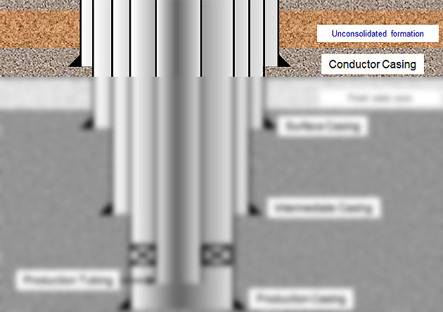
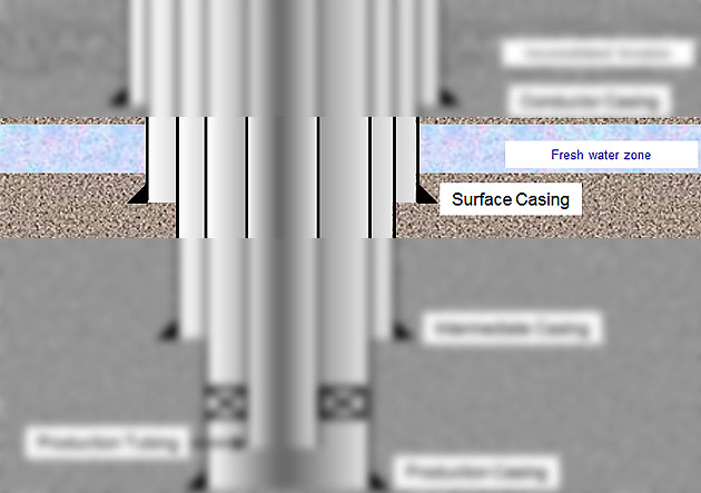
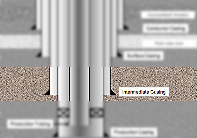
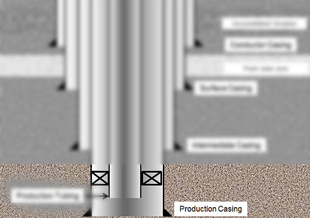
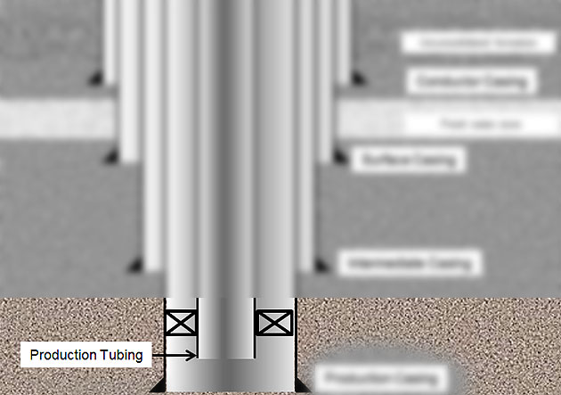
The illustrations below (Figure 1 and Figure 2) are schematics of oil well in general. We will go into details of each casing/tubing based on these two images.

Figure-1---Casing-and-Tubing-String

Figure 1 – Casing and Tubing Schematic without Liner

Figure-2---Casing-and-Tubing-Schematic-with-liner

Figure 2 – Casing and Tubing Schematic with liner

Conductor Casing

The conductor casing is the first string run in the well and its depth range is 40 to 300 ft. In soft formation areas or offshore environment, the conductor pipe is hammered down by a large pipe hammer. In hard rock areas, driving the casing is not doable therefore a larger hole must be drilled to landing depth before running and cement this casing.

Figure-3---Conductor-Casing

Figure 3 – Conductor Casing

Functions of conductor casing are as follows;

  • Protect formation washout at the shallow depth
  • Minimize loss circulation in shallow zones
  • Provide a fluid conduit from the bit to the surface
  • Minimize hole-caving issues. Unconsolidated formations (gravel) will fall into the well resulted in drilling issues.

Surface Casing (Structural Casing)

In some drilling areas, it may require an additional casing string between conductor casing and surface casing. This casing is called “Surface Casing (Structural Casing)” and it is typically run from 500 ft to 1,000 ft. This casing cannot be driven into the well so it requires drilling a hole before running it.

Figure-4---Surface-Casing-(Structural-Casing)

Figure 4 – Surface Casing (Structural Casing)

Functions of surface casing are as follows;

  • Minimize lost circulation in a shallow depth
  • Provide a fluid conduit
  • Provide wellbore integrity to prevent hole-caving
  • Cover weak formations when there is a well control situation
  • Support blow out preventer (BOP) for well control
  • Cover shallow fresh water zones from contamination

Intermediate Casing

The intermediate casing is run after surface casing and there can be several intermediate casing in one well. Drilling intermediate section most of the time requires higher mud weight than normal pressure gradient therefore the primary function of this casing is related to control high mud weight and formation pressure.

Figure-5---Intermediate-Casing

Figure 5 – Intermediate Casing

Functions of intermediate casing are listed below;

  • Protect weak zones at shallower depth while drilling with higher mud weight
  • Provide wellbore integrity for well control
  • Isolate some formations which can cause drilling issues as lost circulations, shale sloughing, etc.
  • Support weight of well control equipment
  • Provide a fluid conduit

Casing Liner

Casing liner is widely used in the industry because it is a cost-effective way to run a casing string across open hole length without running all string to the surface. The casing liner can be utilized as intermediate casing or production casing. The casing liner is run into the shallower casing string and the overlap between two strings is typically around 300 – 500 ft.

Figure-6---Casing-Liner

Figure 6 – Casing Liner

Production Casing/Liner

This casing string/liner can be set at a depth above, midway or below the pay zone depending on completion strategies. Primary cement job is very critical for this string because it affects production from the well.

Figure-7---Production-Casing

Figure 7 – Production Casing

Figure-8---Production-Liner

Figure 8 – Production Liner

Functions of production casing are listed below;

  • Isolate production zone(s) from other formations
  • Protect completion equipment
  • Provide a conduit for reservoir fluids
  • Provide annular passage for gas lift injection
  • Contain formation pressure in case of tubing leak

Production Tubing

The production tubing is run into the well after the production casing is in-place and all the completion equipment is run with this string downhole. The tubing must be strong enough to support production load and it should be able to workover in the future.

Figure-9---Production-Tubing

Figure 9 – Production Tubing

Functions of production tubing are listed below;

  • Provide the conduit for oil, gas, water from formation(s)
  • Protect the production casing from corrosion, wear and deposition from the reservoir fluids

 Ref Book -> Applied Drilling Engineering Book special offer 

Piper Alpha The Biggest Oilfield Catastrophe – Oilfield Incidents in The Past

$
0
0

Piper Alpha was basically a North Sea oil production platform, commencing production way back in 1976, run by Occidental Petroleum (Caledonia) Ltd, which initially started oil production and later gas production as well. Unfortunately, it was wrecked and demolished on 6 July 1988, by an explosion which triggered oil and gas fires. It resulted in a lot of destruction, including 167 casualties and only 67 men survived.


History of Piper Alpha


Occidental discovered The Piper Field in the beginning of 1973, following which Piper Alpha initiated production 3 years after. The platform was situated roughly 120 miles towards the north-east of Aberdeen. In the beginning, it only dealt in the production of oil however after a few years, in 1980 with new equipments being installed, gas production was facilitated. Piper Alpha was linked with the Flotta oil terminal on the Orkney Islands by a sub-sea pipeline that was further shared with Claymore platform. Gas pipelines of Piper Alpha linked it to Tartan platform and distinct MCP-O1 gas processing platform. In a nutshell, Piper Alpha had 4 prime transport risers: an oil export riser, the Tartan gas riser, the Claymore gas riser, & MCP-01 gas riser.

Situated around 120 miles north-east of Aberdeen in about 474 feet of water, Piper Alpha was a huge fixed platform inclusive of four modules with distinct firewalls, which was built by McDermott Engineering at Ardersier & UIE at Cherbourg, where the sections were united at Ardersier before tow out in 1975. The modules were placed out in a manner, which would keep any risky or hazardous functions at a good distance from places with personnel. However, this safety precaution was not complied with after gas production started when all the susceptible areas were situated in proximity to each other. The gas compression was located close to the control room that triggered the accident. Crude oil & natural gas was generated from 24 wells and was meant to be transported via 3 distinct pipelines to the Flotta oil terminal on Orkney and other installations. During the hour of the catastrophe, the most intense and heaviest functional platform in the North Sea was Piper along with Magnus & Brae B.

Explosion & Fire of Piper Alpha

A and B, were the two condensate-injection pumps, on which they started working from 06 July 1988. Before the gas was carried and delivered to Flotta, these condensate-injection pumps were utilized for compression of gas on the platform. After a pressure safety valve was extracted from A to facilitate recalibration & re-certification, and the couple of blind flanges were fixed into the pipes, the workers during the dayshift wrapped up.

Towards evening on the same day, pump B stumbled and hence the workers of the nightshift came to a prompt consensus that pump A might be functional again, and once that was done, gas condensate leaked from the two blind flanges. Around 10 p.m. that night, the gas caught fire and burst into flames causing substantial impairment and harm to various other areas with the further release of gas & oil. Almost about half an hour after that, there was a major dysfunction with the Tartan gas riser resulting in another ignition and detonation. At the end of it there was massive fire and the place had burst up in flames. At approximately, 10.50 p.m., there was a major failure in  MCP-01 gas riser due to which there was another catastrophe and similarly, there were various explosions around the place resulting in the final structural breakdown of almost the entire installation.

Due to these disastrous explosions, 167 men lost their lives which included two operators of a Fast Rescue Craft. The remaining 62 men managed to escape and survive by jumping into the sea from the high decks of the platform. In the following years, around 1988 to 1990, the two-part Cullen Inquiry had studied and established the origin and reasoning for the explosions. Recommendations were made for preventive future protocols and the offshore operators consented and implemented about 106 recommendations.


Contributing Factors of Explosion & Fire of Piper Alpha

 Gas and crude oil was persistently and incessantly pumped out by the Tartan & Claymore platforms, and due to management issues in the crew, this was not stopped in spite of knowledge about the harmful repercussions.

  • The chain of command collapsed and there was substantial communication gap to the crew.
  • Another thing that came up was, if or not there was enough time period for better evacuation at the time of the crisis. What actually happened was the people in the crew who were superior and were authorized to give commands for this emergency evacuation were already dead as there was a major blast in the control room as blast walls had not been installed. Further, the platforms which were situated in proximity to Tartan & Claymore went on with pumping gas and oil to Piper Alpha, and subsequently the pipeline cracked and burst due to extreme temperature of the second blast. The personnel thought they were not authorized to cease the production in spite of the apparent crisis.
  • The fire-walls which were present from the beginning had not been updated to blast walls after the major alterations in 1980.
  • About 20 days after this incident, the debris after the explosion was finally extinguished by a squad headed by firefighter Red Adair, in spite of the weather forecast of 80 mph winds & 70-foot waves. The area where almost about 100 crew members had used as a protection at the time of the calamity was retrieved from the sea bed towards the end of the year with 87 dead bodies.
  • The Lowland Cavalier, a diving support vessel which was in proximity to the place of the calamity stated and reported the first explosion just prior to 10 p.m., and around half an hour following the first explosion, the second one took place. Till the rescue helicopters arrived, combustion and fire resulted in flames as high as 100 meters, which could be spotted from about 100 km (120 km from the Maersk Highlander). About 37 out of 59 crew members were rescued by the Fast Rescue Craft MV Silver Pit; coxswain James Clark was later decorated with George Medal. Others who got the George Medal were Andrew Kiloh from Aberdeen, Charles Haffey from Methil, & James McNeill from Oban.

Casing Design Overview – Overall Process of How To Do Casing Design in Oil and Gas Industry

$
0
0

After understanding the basic of each casing string run in oil wells, we will go into casing design overview. This article will give you general ideas of casing design.

casing-Design-Overview

Casing Design Objectives

The items below are design objectives for well constructions which drilling engineers must consider.

  • Design must meeting production strategies.
  • Design must provide mechanical integrity based on anticipated load cases which will be encounter during life time of the well.
  • Cost of well must be economic.
  • Design must provide ways to be able to plug and abandon the well at the end of wells life.

These objectives are generic and your wells may have additional objectives based on business needs.

Data Required for Casing Design

The following items are information require for casing design.

  • Production Information

o   Type of packer fluid

o   Density of packer fluid

o   Type of reservoir fluid

o   Expected flow rate, pressure, temperature of the well

o   Sour gas (H2S, Co2)

o   Maximum production load case

o   Completion strategies

  • Geological Data

o   Pore pressure

o   Fracture pressure

o   Formation temperature

o   Formation type and structure

o   Plan for logging programs

o   Location of problematic zones as possible loss zones, high permeable zones, unstable zones, shallow gas hazard, fresh water zones, sour gas (H2S, CO2) zones, etc

  • Directional Data

o   Geologic targets

o   Surface location

o   Anti-Collision issue

  • Production plan

o   Size of casing and tubing met required production rate

o   Completion equipment (packer, SCSSV, gas lift valves, etc) planned to run into the well

  • Government regulation

o   Each country has different requirement for drilling oil wells.

  • Equipment supply and logistics

o   International or local suppliers for casing

o   Logistics and tax for equipment

Design Phases

There are two phases of design. The first on is a preliminary design and the second one is a detailed design.

Preliminary Design Phase

After gathering information required, you will do the first phase of casing design. The preliminary design will give you all scopes of the project (well construction plan). The following scopes are results from this phase.

  1. Casing setting depth and number of strings – The following factors used to determine casing setting depths.

o   Pore pressure and fracture gradient – Based on the pore pressure and the fracture gradient of the well, you will be able to determine how many strings required and where each string needs to be set. There are two approaches which are top down design and bottom up design. We will go into details of this topic later on.

o   Differential sticking zones – potential sticking formations should be cased off before going deeper because the deeper depth requires higher mud weight which will result in more serious of pipe stuck issue.

o   Wellbore stability – this is the same concern as the differential sticking. Right type of mud and weight will minimize this issue.

o   Formation pressure / fracture gradient prediction uncertainty – drilling into unknown areas has a lot of uncertainty regarding pore pressure / fracture gradient prediction. Therefore, additional string must be considered to run as a contingency string.

o   Directional concern – Typically casing is set after a building section of the well in order to mitigate a key seat issue while drilling deeper.

  1. Drilling fluid program – drilling fluid weight is the most critical factor in the casing design. Mud weight should be sufficient enough to drill to planned depth without fracturing formation at shallower depth. Moreover, drilling mud for each section needs to meet drilling objectives as hole cleaning, wellbore stability, formation evaluation, minimizing formation damage, etc.
  2. Drilling equipment needed – drilling equipment is one of the factors which need to take into account carefully. You should ask yourself about drilling equipment:

o   What is the specification of the drilling rig?

o   Can the rig work with the casing plan?

o   Does the rig have enough power to provide hydraulic power to downhole tool, clean the hole, etc?

o   Do we have the well control equipment fit for the operation?

o   What size of downhole tool do you need to drill the well?

  1. Production equipment – equipment required for production which you need to consider is listed below;

oType, size, grade, etc of production tubing

oCompletion equipment as sub surface safety valve, gas lift valve, submersible pump, down control valve, etc

o Gravel pack and frac pack

Especially, nowadays many companies tend to run smart completion in order to prolong well life and optimize well production. This will require a lot of clearance between completion string and production tubing. It might affect the casing size big time.

  1. Formation evaluation – this relates to tool size and drilling fluid used in that section which you need to evaluate reservoir.
  2. Top of Cement (TOC)TOC will have effect on load design and typically TOC design is based on the following criteria;

o   Regulatory requirement

o   Zonal isolation

o   Formation strength

o   Buckling

o   Pressure build up in the annulus

Detailed Design Phase

In this phase, engineers will go into detailed calculations in order to select casing/tubing (size, grade, connection, etc) for all strings based on the preliminary design.  The engineers will design each string of pipe by using design criteria which consist of design factors and load cases.

Load cases for casing design are as follows;

  • Burst load
  • Collapse load
  • Production load
  • Drilling load
  • Running and cementing load
  • Tri axial load

We wish you would get some idea regarding the over process of casing/tubing design. The next step, we will go into details on several topics so you will have more understanding and be able to do some calculations.


 Ref Book -> Applied Drilling Engineering Book special offer 

4-Way Valve Operation in Blow Out Preventer Accumulator (Koomey) Unit

$
0
0

4-way valves in the accumulator (Koomey) unit are used to control the position of Blow Out Preventer (BOP). Today we will go into the detail of 3 positions of 4-way vales in order to see how each position affects to the BOP.

4-way valve operation fb

Read more details about Koomey Unit here =>mechanism of Koomey unit.

Four-Way Vale in Open Position

When the valve is turned into the open position, it directs hydraulic pressure from the manifold into the BOP openning port therefore the BOP is in the open position. The hydraulic fluid in the ram closing chamber will return back to the reservoir tank. Figure 1 illustrates how the hydraulic pressure is lined up to open the BOP.

 4-way-vale-open-rams

Figure 1 - Open position of the 4-way valve


Four-Way Vale in Closed Position

The valve is turned into the close position. It means that the hydraulic pressure from the manifold is transferred into the BOP close port. The hydraulic from the opening chamber will return back to the reservoir tank. Figure 2 shows how the hydraulic pressure is lined up to close the BOP.

4-way-vale-closed

Figure 2 - Closed position of the 4-way valve

Four-Way Vale in Block Position

When the four-way valve is left in the block position (central position – Figure 3), there is no hydraulic pressure going into either the “close” or “open” port in the BOP.  You might not know exactly the position of the rams with the block position.

 4-way-vale-block-rams

Figure 3 – Block position of the 4-way valve

In normal drilling operation, you should never leave in the block position. However, the valves can be left in the block position during rig move and repairing operation.

There is one special thing which personnel must consider about the handle of 4-way valve used to operation the bilnd/shear rams (Figure 4). The control handle must be protected to mitigate unintentional operation however it still allows to be remotely operated from the BOP remote control panel.

blind-shear-ram-handle

Figure 4 - Blind/shear ram 4-way valve handle

Reference books: Well Control Books

Basic Knowledge of Kelly and Top Drive VDO Training

$
0
0

Kelly or Top Drive is the drilling equipment which transfer both rotational and compression force to the bit in order to make a hole. This vdo training demonstrates the basic understanding for kelly and top drive. Additionally, we add full transcript of this vdo in order to help people learn about this topic effectively. We wish you would enjoy watching and learning from this vdo.

Full Transcript of this multimedia training. 

kelly-and-top-drive

Many pieces of equipment make up our Rotary drilling rig. Part of it’s on the surface and part of its underground or subsurface. All the equipment has one main purpose, to put a bit at the bottom of the hole where it can drill or make holes.

To put the big on the bottom, rig crewmembers screw it into a special pipe. The pipe is called the Drill String. Crewmembers lower the drill string and attached bit into the hole. For the bit to drill, surface rig equipment has to rotate it unless it’s rotated by a mud motor. Equipment also has to put weight on it to force the bit’s teeth cutters into the formation. As the bit rotates, a circulating fluid has to take the drill cuttings away from the bit. Otherwise the hole would clog up. This fluid which circulates is called drilling mud.

Imparts Rotary motion the drill string so that the bit can turn, either at Top Drive or a Kelly and Rotary table system is used. Power is transferred from the surface down hole via the drill string. Some rigs rotate the drill string with a top drive unit. Top drives are expensive but very efficient. Crewmembers can add drill pipe joints to the drill string very quickly and safely and they can drill the well more efficiently with less chance of sticking the drill string in the hole as compared with the Kelly and Rotary Table.

A powerful motor turns a driveshaft which is connected to the top drive. Crewmembers makeup, or attach the drill string to the driveshaft. The driveshaft turns the drill string and bit. Notice that the drill string goes through an opening in the Rotary table. The table does not however rotate. A link system suspends the Top Drive unit from the rigs straddling block.

Drilling mud enters the unit through the goose neck to the Rotary Hose, the flexible line that conducts drilling mud from the pump.  A motor and Gear box power the main drive shaft.  The crew makes up the drill string to the drive shaft. The built in, inside, blow out preventer, IBOP or safety valve, keeps fluid from back flowing up the drill string when the driller closes it.

The crews use the torque wrench assembly to make up and break out, connect and disconnect the drill string. The elevator links suspend the elevator. The drill crew lashes the elevator around the drill string to allow the Top Drive unit to lift It up or down.

A Kelly, a Kelly-drive bushing, a master bushing and a rotary table rotate the drill string and bit on some rigs. The Kelly is a heavy tubular device. It usually has either four or six sides. That is, it either has a square or a hexagonal cross-section. Square Kellys are less expensive than hexagonal ones but the hex Kellys are stronger so rigs drilling deep holes often use them. Whether four or six sided, crew  members attach or make up the Kelly to the top joint of pipe in the drill string.

The Kelly, four sided or square in this example, moves through a square opening in the Kelly-drive bushing. The Kelly-drive bushing mates with the master bushing which the rotary table turns. This rotates the entire drill string and attached bit. The Kelly moves down  as the hole deepens.


Casing Seat Selection – How To Select Casing Setting Depth

$
0
0

From the previous article, you’ve learnt about overall of casing design process and in this article we are going to discuss about how to select casing setting depth. The selection of casing string and setting depth is based on formation pore pressure and fracture gradient of the well.

casing seat selection fb

For the casing setting depth determination, pore pressure and fracture gradient are normally described in PPG (Figure 1).

Figure-1---Pore-Pressure-and-Fracture-Pressure-Plot

Figure 1 – Pore Pressure and Fracture Pressure Plot

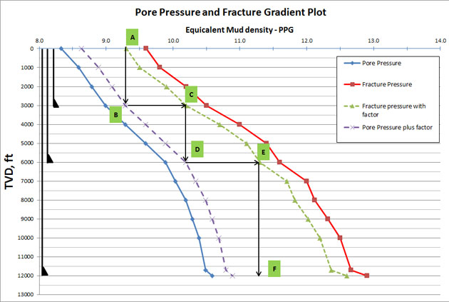
 The solid lines in the chart are not accounted for safety factor; therefore, for the first step of casing seat design, safety margin must be applied. For this example, we will add 0.3 ppg for safety for both pore pressure and fracture gradient (Figure 2). You need to add the safety factor into formation pressure and subtract it from the fracture gradient. What’s more, the safety factor value may depends on where you work and how much confident in your data.

Figure-2---Pore-Pressure-and-Fracture-Pressure-Plot-with-Safety-Margin

Figure 2 – Pore Pressure and Fracture Pressure Plot with Safety Margin

The dashed lines are design range which will be used for the design. There are two ways to determine casing setting depths which are bottom-up and top-down method.

Bottom Up Casing Design

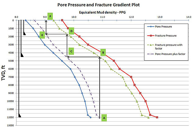
This design will start from the bottom of the well up to surface and the setting depths are designed within the safety factor limits (dotted lines). Starting at the bottom (formation pressure dashed line – Point A), draw a vertical line upward to fracture pressure dashed line – Point B (Figure 3). Casing should be set from 4,500’ TVD to 12,000’ TVD because you can reach TD (12,000’ TVD) with highest equivalent mud weight and you will not break the formation at shallow depth (4,500 TVD). We will apply this same concept to another string.

Figure-3---Bottom-Up-Design-Step-1

Figure 3 – Bottom Up Design Step#1

The next casing string is determined by drawing a horizontal line from Point B to intersect the pore pressure dashed line at Point C. Then draw a vertical line from Point C to the fracture gradient dashed line at Point D (Figure 4). The Casing must be set from 1,800’ TVD to 4,500’ TVD.

Figure-4---Bottom-Up-Design-Step-2
Figure 4
– Bottom Up Design Step#2

With the same idea, the next casing string is determined by drawing a horizontal line from Point D to Point E and a vertical line from Point E to Point F (Figure 5). The Casing must be set from surface to 1,800’ TVD.

Figure-5---Bottom-Up-Design-Step-3

Figure 5 – Bottom Up Design Step#3

Based on the bottom up design concept, we will need to have 3 strings of casing set at 1800’ TVD, 4500’ TVD and 12,000 TVD (Figure 6).

Figure-6---Bottom-Up-Design-Final

Figure 6 – Bottom Up Design Final

From the example, you can see how the bottom up casing design process is done. If you have the different pore pressure/fracture gradient, you can repeat the process for other casing strings until you reach surface casing.

Top Down Casing Design

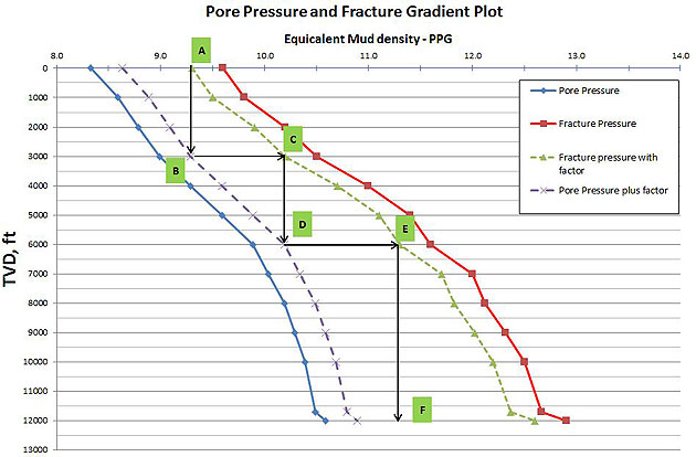
This design will start from the surface of the well down to the bottom and the setting depths are designed within the safety factor limits (dotted lines). We start by drawing the vertical line from the facture gradient dashed line (point A) down to pore pressure dashed line (point B). See Figure 7. The first casing should be set from surface to 3,000’ TVD.

Figure-7---Bottom-Up-Design-Step-1

Figure 7 – Top Down Design Step#1

Next, draw the horizontal line from Point B to Point C located in the fracture dashed line curve. Then draw the vertical line from Point C to intersect the formation pressure dashed line curve at Point D. This is the section casing string which should be set from 3,000’ TVD to 6,000’ TVD (Figure 8).

Figure-8---Top-Down-Design-Step-2

Figure 8 – Top Down Design Step#2

Applying the same concept to the next string, draw the horizontal line from Point D to intersect the fracture gradient with safety factor chart at Point E and draw the vertical line from Point E to the target depth at Point F. The last casing string should be set from 6,000’ TVD to 12,000’ TVD (Figure 9).

Figure-9---Top-Down-Design-Step-3

Figure 9 – Top Down Design Step#3

 Based on the tow down design concept, we will need to have 3 strings of casing set at 3,000’ TVD, 6,000’ TVD and 12,000 TVD (Figure 10).

Figure-10---Top-Down-Design-Final

Figure 10 – Top Down Design Final

From the example, you can see how the top down casing design process is done. You can repeat the same process to determine the setting depth based on your fracture and pressure plot.

 Ref Book -> Applied Drilling Engineering Book special offer 

Petrobras P-36 Sinking – The Biggest Oil Rig Sinking In the Oilfield Industry

$
0
0

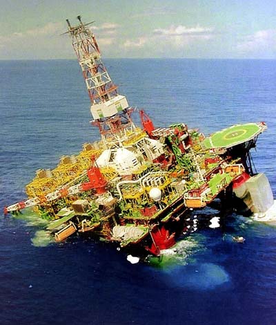
Petrobras P-36 – This incident cost several million us dollars and it’s worthy to learn from it. One of the biggest global floating semi-submersible oil platforms Petrobras 36 (P-36), which was owned by Petrobras, an oil company in Brazil with its base of operations at Rio De Janeiro was destroyed after 20th March 2011 when it sunk. The platform was then approximately valued at US$350 million. Its current value is US$466 million. Constructed and erected as a drilling rig in the year 1995, at the Fincantieri shipyard (Genoa, Italy), was owned by SocietàArmamentoNaviAppoggioS.p.A. The rig, which was a good 33,000 tonnes was transformed to the biggest global oil production platform by Davie Industry, Levis, Canada. P-36, which was functioning for Petrobras, about 130 kms off the coast of Brazil on the Roncador Oil Field daily generated approximately 84,000 barrels (13,400 m3) of crude oil. P-36 was substituted by a chartered vessel from SBM Offshore, FPSO-Brasil, which is in a lease contract with Petrobras since Dec 2002. Formerly known as ‘Spirit of Columbus’, the P-36 was built and assembled in Italy for 10 years from 1984 to1994. The platform was crafted as a floating production unit and was based upon a conversion of the Friede & Goldman L-1020 Trendsetter-type semi-submersible. Later, it was revamped and re-crafted for Petrobras from around 1997 to 1999 and was functional in May 2000 in the Roncador Field off the Brazilian coast. It had the capacity to process daily about 180,000 bopd & 7.2 million cubic meters of gas. On May 2001, the P-36 began to generate daily approximately 84,000 barrels of oil & 1.3 million cubic meters, after which there were two blasts and following the explosions, it sank. Platform Loss

 On 14th March 2001, almost around 10.30 p.m., drainage functions commenced on the portside EDT (emergency drain tank), one of the two 450 cubic meter tanks (one port, one starboard), and they were utilized for storing oil and water at the time of maintenance or any emergency. On 15th March, at around 12.30 a.m., there was a blast in the starboard aft column possibly due to the mechanical cracking of the starboard EDT, which resulted in the discharge of water saturated with gas as well as oil into the aft starboard column and this resulted in the platform listing 2 degrees in no time. After this, there was another blast resulting in 10 casualties and one fire-fighting crew member being seriously injured. The consequent platform impairment and damage resulted in flooding in aft starboard column compartments & pontoon tanks, and this enabled passage of sea water via open sea chest valves. On the morning of 15th March at around 8.15 a.m., the platform listed 16 degree, which immersed the chain lockers apertures on the main deck level and resulted in a progressive list casing loss of platform. Out of the 175 members, 138 were vacated by crane to boat on 15th March from 1.44 a.m. to 4.20 a.m. and the rest of the people were vacated at around 6.00 a.m. on 15th March by helicopter because the platform was unsteady and destabilized. For a couple of days after the catastrophe, a lot of efforts were directed towards alleviating and making the platform constant by infusing nitrogen in a vent line, which was close to the broken column, however due to unpleasant weather conditions, it was interrupted. Finally, at 11.40 a.m. on 20th March, the platform overturned and then it sank in 1300 m of water, due to which salvaging the unit was a herculean task.

Conclusions When the platform submerged in the water, it had approximately 9500 bbls of oil on board, and about 2200 bbls of oil seeped out within just a day. Following this there were procedures and functions to dissolve the oil with chemicals and to obtain the oil back were undertaken in order to reduce the harmful impact of the incident. Det Norske Veritas framed and confirmed The Petrobras Inquiry into the P-36 sinking and it listed a detailed analysis of the series of episodes resulting in the P-36’s loss. Listed below were the possible reasons which triggered the catastrophe:

  • Port EDT’s configuration to the Production Header rather than the Production Caisson, which enabled hydrocarbons making its way into the starboard EDT;
  • The unanticipated oil and gas circulation along with water under pressure via entrance valve of starboard EDT, which triggered overpressure;
  • The fissure of the starboard EDT, resulting in leakage of oil, water & gas that resulted into an overflow in the starboard column;
  • Further overflow caused in the starboard column due to the fissure of the service sea water pipe in starboard column;
  • Passage of gas  to the elevated places of the starboard column through doors & ventilation hatches;
  • A source of detonation which resulted in the blasting of the gas cloud;
  • Two fire-fighting pumps which were instigated and started resulting in an overflow through the fissured sea water pipe;
  • The breakdown of watertight dampers, causing water to attack all aft starboard pontoon rooms, along with the pump room, water injection room, propulsion room, & access tunnel;
  • The water accessibility which resulted in dysfunctioning of the seawater pump, and the intake valves to sea-chest were not shut;
  • There was more overflow and flooding through the open sea-chest valves which triggered a progressive platform list;
  • The drowning of the chain locker pipes at the main deck level, resulting in down-flooding;
  • Persisting gradual flooding of the starboard aft pontoon tanks & deck box compartments, till water finally gushed out and started overflowing in the central caisson resulting in the drowning of the platform

The primary causes were:

  • Port EDT’s configuration to the Production Header instead of to the Production Caisson, which enabled hydrocarbons making its way into the starboard EDT;
  • The holdback in activating the port EDT drainage pump, permitting the reverse flow of hydrocarbons for approximately 60 minutes;
  • The breakdown of activators to shut ventilation dampers, which triggered the overflow of water into the starboard column & pontoon compartments;
  • Two sea water pumps were still a work-in-progress with no contingency in case of a catastrophe;
  • Insufficient planning for damage control and planning for working through a drastic emergency & stability control situations.

 Ref: en.wikipedia.org/wiki/Petrobras_36, home.versatel.nl/the_sims/rig/p36.htm

Casing Size Selection – How To Select Casing Size to Match the Drilling and Completion Goal

$
0
0

We’ve learnt several topics in regard to casing design and this article will demonstrate you how to determine casing size in the well.

casing-size-selection-cover

Casing size selection is determined from the inside outward and it starts from the bottom hole.

The sequence of design is based on the following steps;

1. Proper sizing of tubing is determined by inflow performance analysis.

2. Completion equipment is planned to install with tubing string. Determine which part has the biggest OD. This will directly impact of production casing.

3. Bit size for drilling the production section.

4. Casing size must be smaller than bit size and its ID must be bigger than the biggest component in completion string.

5. Once you get the last casing string, the upper string is selected by repeating bit selection and casing selection similar to step #3 and #4.

You may need to use the following table (Table 1) to determine bit size and casing size. This is based on API casing therefore if you use special casing, you may need to check with the casing company to give you exact casing ID.

Table 1 - Commonly Used Bit Sizes That Will Pass Through API Casing

Table 1 - Commonly Used Bit Sizes That Will Pass Through API Casing

Example: According to the previous example, this is the casing design based on pore pressure and fracture gradient (Figure 1).

Figure-1--Casing-Design-Based-On-Pore-Pressure-and-Fracture-Gradient
Figure 1- Casing Design Based On Pore Pressure and Fracture Gradient

The casing string should be set at 3000’ TVD, 6,000’ TVD and 12,000’ TVD.

The Rig needs to drill and set the conductor casing to 500’ TVD in order to rig up the well control equipment.
Completion information

• Tubing string – 3-1/2” tubing
• Completion equipment – TRSV, Side Pocket Mandrel, Packer, etc.
• The biggest size of completion equipment is 5 inch.

According to the Table 1, the bit and casing plan for this well is described below.

Note: this plan is based on size selection only. The load cases are not accounted for in this example.

Production Section
Bit size = 8-1/2”
Casing = 7”, 26 ppf, ID 6.276”

Intermediate Section
Bit size = 12-1/4”
Casing = 9-5/8”, 40 ppf, ID 8.835”

Surface Section
Bit size = 14-3/4”
Casing = 13-3/8”, 48 ppf, ID 12.715”

Conductor Casing
Bit size = 17-1/2”
Casing = 16”, 55 ppf, ID 15.375”

Figure-2-–-Casing-Details

Figure 2 – Casing Details

In order to determine what casing grades to be used in the well, you need do the detailed calculations based on several load cases as burst, collapse, tensile, etc. We will cover the details later on.

 Ref Book -> Applied Drilling Engineering Book special offer 

Oil & Gas Well Casing – VDO Training

$
0
0

There are several articles discussing about casing design and we would like to share you this excellent VDO training in this topic “Oil & Gas Well Casing”. This VDO contains the basic over view of casing starting from surface to production section.  You will see nice illustrations which help you get clearer picture on this topic and we also add full VDO transcripts to provide assistance to some learners who cannot catch the content in this VDO clearly.

Oil & Gas Well Casing – VDO Transcript

oil-Gas-Well-Casing

By the time the crew drills the well to depth, it usually has several strings of casing in it. These strings are called conductor casing, surface casing, intermediate casing and production casing.

Notice that cased well looks something like a telescope pulled out of full-length but it is as the crew drills the well deeper, the size of the whole and the size of the casing gets smaller in diameter. Almost always, the drilling contractor cannot begin drilling at the surface and go all the way to total depth in one step.

For one thing, formations near the surface tend to crumble and cave-in easily so conductor casing prevents cave-ins. For another thing, formations near the surface may also hold freshwater that the well cannot contaminate. So surface casing prevents freshwater zones. For still another thing, deep formations are sometimes so-called troublesome formations. That is, they can be drilled by adjusting the properties of the drilling mud but once drilled, need to be sealed off to prevent problems in drilling the deeper portions of the well. So, intermediate casing seals of troublesome zones. Sometimes, deep wells required more than one intermediate casing string. Finally, once the producing zone is drilled, it needs to be protected and sealed; so production casing isolates the producing zone. The first string of casing is the conductor casing.

The hole drill first is pretty big; often as much as 36 inches or more as, almost a meter in diameter. The conductor hold has to start out with a big because as drilling goes on, the hole’s diameter decreases. In some cases, the rig will hammer the conductor casing in place if the ground near the surface is really soft. If the conductor hole is drilled, the casing is cemented in it. Using a bit whose diameter is small enough to easily go inside the conductor casing, the rig drills the cold below the conductor to a prescribed depth.

The diameter of the surface hole can still be relatively large; say 17 inches, over 400 mm or even more. The surface hole’s depth is usually set by regulatory agencies. They require that the surface hold a drilled through all freshwater zones and that surface casing be set and cemented to protect the zones from damage by additional drilling operations. This depth could be from hundreds to thousands of feet or meters. Normally, crew-members nipple up or connect the BOP’s to the surface casing at the well head. So this casing must be strong enough to support the BOP stack. In addition, it has to withstand the gas or fluid pressures the well may encounter. Surface casing, also has to be strong enough to support the addition of casing strings hung inside of it.

To drill the intermediate hole, the operator chooses are still smaller in diameter bit which easily fits inside the surface casing. A bit of about 12 inches or 300 mm in diameter, is one example of the size. Intermediate casing is also cemented into place to seal off troublesome formations like moss circulation zones or abnormally pressured zones. It is often the longest section of casing in the well; Also the crew connects or nipples of the BOP’s to the top of the intermediate casing by using an adapter and casing head or a drilling spool which is stacked on or connected to the top of the surface casing wellhead. It therefore anchors the BOP’s for the drilling that comes later. Remember, that the crew has to nipple up a stack of BOP’s to each string of casing that is run into the well; first they nipple up on the surface casing then on the intermediate casing and finally on the production casing.

To drill to final depth below the intermediate casing, the rig owner selects a bit whose diameter is small enough to fit inside the intermediate casing; say from 8 to 10 inches or 200 to 215 mm. This part of the hole penetrates the producing zone. When cemented in place, production casing seals off the producing zone and readies it for production. Production casing also houses and protects the tubing and other equipment used to produce the well. The operator usually perforates, puts holes in this casing when the well is completed or ready for work to begin.

Well completion is the term describing the activities and methods of preparing the well for production of oil and gas. Oil and gas flow into the well through the perforations. Sometimes well owners run liners instead of casing into the well. A liner, is a shortened the string of casing used the case the smaller open hole section below an existing casing string in the hole. It’s just like casing, except that a liner does not run all the way to the surface. Instead, the casing crew hangs it from the bottom of the previously run casing or liner string using a special piece of equipment called liner hanger. In this case there is an intermediate liner and a production liner. Using liners saves money since they do not extend to the surface.


Bullheading Well Control Method

$
0
0

Bullheading is one of the well control methods which may be utilized in some occasions in order to control the well. Concept of bullheading is to pump kicks back into formations by using kill weight fluid. People usually use this method when normal circulation is impossible and volumetric method is not feasible to perform.

bullheading-Well-Control-Method-cover

When May You Consider Using the Bullheading Well Control Method?

  • When the kick size is very big so you may not be able to control the excessive volume coming to the surface.
  • When you need to reduce surface pressure in order to start further well control operations.
  • When there is a possibility to exceed surface pressure and volume gas on the surface if the conventional methods (drillers’ method, wait and weight and volumetric) are performed.
  • When there is no pipe in the hole while taking influx.
  • The influx contains high level of H2S which can cause safety of personnel on the rig.
  • When there is no feasible way to strip back to the bottom in order to kill in the flux below.

For every drilling operation, decision to perform bullheading must be discussed because if the well is shut in and wait for a long time before making decision to bullhead the well, it might be very difficult to perform because the surface pressure at that time may increase so high due to gas migration. The chance of pushing the kick back into reservoir becomes smaller.

 Note: Bullheading may or may not fracture formations.

There are some factors affecting the feasibility of bullheading as listed below;

Reservoir permeability – pumping fluid back into low permeability reservoir takes longer time than pumping into high permeability zone. It might require breaking the formation in order to successfully bullheading the well.

Surface pressure rating – rating of surface equipment as BOP, wellhead, casing, etc will limit the maximum allowable pumping pressure.

Type of influx – Gas influx will migrate and it will increase surface pressure, however, liquid influx (oil or water) will not cause increasing in surface pressure because it will not migrate.

Procedure of Bullheading (Example)

This procedure below will give you only overview of how to perform bullheading therefore you must need to add the site specific information before conducting the actual work.

  1. Determine surface pressure limitation of surface equipment.
  2. Calculate surface pressure which will fracture formation during  bullheading operation.
  3. Prepare a bullheading pressure chart representing strokes pumped vs pumping pressure.
  4. Ensure correct line up.
  5. Bring the pump to speed at low rate to overcome surface pressure.
  6. Slowly increase pump rate to the planned pump rate.
  7. Closely monitor tubing, casing pressure to ensure that pressures will not exceed the equipment limitation at any stage of operation.
  8. Slow down pump rate when the kill fluid close to reservoir. You will see surface pressure decrease over time while pumping kill mud into the well because the kill weight mud will increase hydrostatic pressure.
  9. Observed pressure increase when the kill weight fluid is pushed into formation.
  10. Shut the pump down and shut in the well.
  11. Monitor pressure. Bleed trapped pressure if required.

We wish you would get more understanding about the bullheading well control. Additionally, we will demonstrate some calculations related to this topic. Please feel free to leave any comments.

Reference books: Well Control Books

Viewing all 497 articles
Browse latest View live


<script src="https://jsc.adskeeper.com/r/s/rssing.com.1596347.js" async> </script>