Quantcast
Channel: Drilling Formulas and Drilling Calculations
Viewing all 497 articles
Browse latest View live

How Much Force Applied to Rig Tong To Get The Right Torque at The Connection

$
0
0

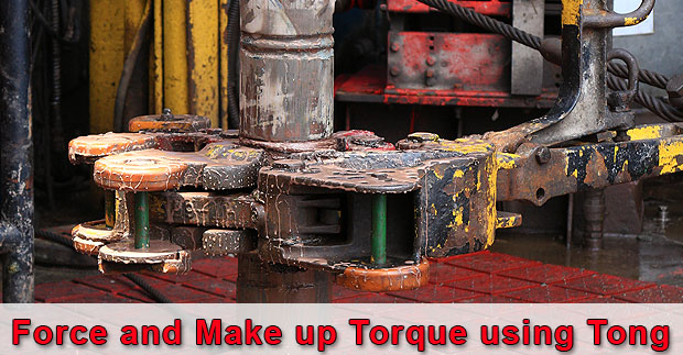
One application of the rig tong is to use to make up connection. The question is asked about how to get the right torque value to the connection if you use the rig tong because you will not see the torque value on the gauge.

force-and-make-up-torque-with-tong

This article will describe how to determine the correct force applied to get the correct torque value when you use the rig tong to make up the connection.

This formula below is used to determine torque value.

rig-tong

Torque = Force x Length of the tong

Where;

Torque in ft-lb

Force in lb

Length of the tong in ft

Force is perpendicular to the tong length. The illustration below demonstrates the direction of force.

Example: Connection 4-1/2” IF – required make up torque = 30,700 ft-lb.

Tong length is 4 ft

rig-tong-example

How much pulling force do you require to achieve the required make up torque?

Torque = Force x Length of the tong

Re arrange the equation:

Force = Torque ÷ Length of the tong

Force = 30,700 ÷ 4.0

Force = 7,675 lb

Ans: 7,675 lb pulling force is applied to 4-ft tong in order to get the torque at connection at 30,700 ft-lb.

 Ref Book -> Applied Drilling Engineering Book special offer 


Rig Engine Power Consumption and Engine Efficiency

$
0
0

In this article, we will focus on the rig engine power consumption and overall engine efficiency and there are few examples for you to get more understand on how to use the formulas as well.

Rig-Engine-Power-Consumption-and-Engine-Efficiency


Input Power of Engine

The formula is listed below;

input power

Where;

Pi = input power in horse power (hp)

H = fuel heating value in BTU/lb

Qf = fuel consumption rate in lbm/hr

Fuel Consumption

The formula is listed below;

Fuel Consumption formula

Where;

Qf = fuel consumption rate in lb/hr

N = rotary speed of engine in revolution per minute, rpm

T = output torque, ft-lb

n = engine efficiency

H = fuel heating value in BTU/lb

Output Power of Engine

The formula is listed below;

 output power consumption

Where;

N = rotary speed of engine in revolution per minute, rpm

T = output torque, ft-lb

Engine Efficiency

The formula is listed below;

engine efficiency formula

Example#1: Rig engine runs at 1,600 rpm and the average output torque is 1,900 ft-lb. The engine consumes fuel about 200 lb mass per hour. Heating value of the fuel is 20,000 BTU/lb.

From the given information, determine the following values;

  • Input Power (Pi)
  • Output Power (Po)
  • Engine Efficiency

Input Power (Pi)

pi example 1

Pi = 1572 hp

Output Power (Po)

po - example 1

Po = 579 hp

Engine Efficiency

engine efficiency - example 1

Efficiency (%) =36.8 %

Example#2:  Diesel engine on the rig runs at 1,700 rpm and its output torque is 2,500 ft-lb. The average engine efficiency is about 35%.

Diesel fuel data: Heating value = 20,000 BTU/lb. Price per gallon = 1.1 $/gal. Weight = 7.15 lb/gal.

Determine daily fuel cost from the rig diesel engine based on the given information.

Output Power (Po)

po - example 2

Po = 809 hp

Input Power (Pi) based on the engine efficiency

pi example 2

Pi = 2,311 hp

Based on the input power formula, we can determine fuel rate consumption.

input power

Re-arrange the equation


Qf - example 2-2

Qf - example 2-3

Qf = 292 lbm/hr

Convert Qf from lbm/hr to gal/day

Qf - example 2-4

Qf = 980 gal/day

Total fuel cost = Qf x Fuel price

Total fuel cost = 980 x 1.1 =1078 $/day

Reference book => formulas-and-calculationFormulas and Calculations for Drilling Operations 

Sedco 135F – IXTOC I Blowout and Oil Spill

$
0
0

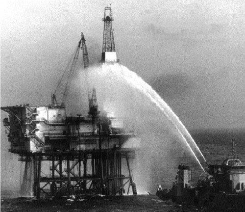
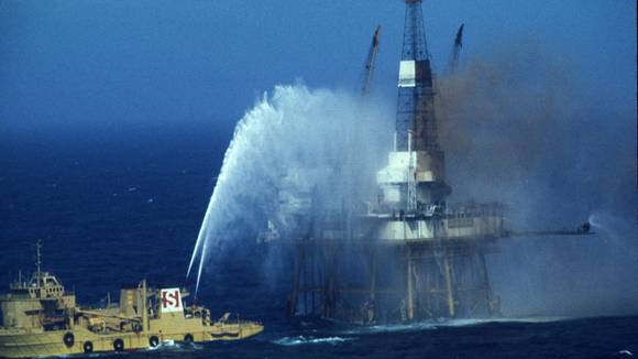
We learn from the past in order to prevent the bad incidents to be happened. This time we would like to discuss about Sedco 135F – IXTOC I Blowout and Oil Spill.  The Sedco 135F was perforating and drilling the IXTOC I well in 1979 for PEMEX, which is a petroleum company in Mexico owned by the state at the time when the well underwent an eruption. Through a drilling, the well had been dug up to 3.6 km with the 9-5/8″ casing set at 3.6 km. It has been vindicated by various studies that there was a failure in mud circulation (essentially mud is a massive and heavy weighted drilling fluid which is utilized as a lubricant for the drill bit, helps in cleaning the drilled rock from hole and present a column of hydrostatic pressure as a prevention from influxes), hence a consensus was reached that it is the best to pull the drill string & plug the well. The absence of mud column’s hydrostatic pressure triggered an unconstrained and liberal circulation of oil & gas to the surface, and this was what happened when the crew was working with drillstring’s lower part. The BOP was shut on the pipe however it was unable to chop the chunky drill collars, permitting oil and gas to come up to the surface where it burned and inflamed the Sedco 135F. The rig broke down and drowned on top of the wellhead space on the seabed, cluttering the seabed with debris like the rig’s derrick & 3000m of pipe.

Sedco-135F---IXTOC-I-Blowout-and-Oil-Spill-2

Sedco 135F – IXTOC I Blowout

At first the circulation in the well was 30,000 barrels/day (1 barrel = 42 US gallons = 159 liters) that later came down to approximately 10,000 bpd by trials to plug the well. Besides, couple of relief wells were dug and drilled to subdue some pressure and finally the well was killed 9 months later on March 23rd, 1980. The squirt and spill from the explosion caused extreme contamination (by June 12th, the oil slick measured around 180km by 80km), approximately 500 aerial missions were sent to spray dispersants on the water. The winds existing resulted in a lot of damage along the coastline of the country and Texas underwent the maximum damage out of all the states. The IXTOC I catastrophe was the most massive single spill, with a release of approximately 3.5 million barrels of oil.

Sedco 135F - IXTOC I Blowout and Oil Spill

Impacts of the spill

The explosion resulted in loss of oil which triggered pollution of a substantial area of the offshore place in the Gulf of Mexico and most of the coastal zone, that is, beaches & barrier islands wrapping around the shallow lagoons.

It was speculated that the oil on the beaches of Mexico in beginning of September was computed to approximately 6000 metric tons. As per the research and studies it was stated that, about 5 times that that figure is predicted to represent an approximate value. Further researches and studies by coastline of Texas vindicate that about 4000 metric tons of oil, that is almost 1 percent was precipitated. The remaining quantity of oil, that is approximately 120,000 metric tons or 25 percent, drowned into the Gulf.

The oil had a massive effect on the littoral crab & mollusk fauna of the contaminated beaches. It resulted in the extinction of various crab species in a vast location, for instance Ocypodequadrata (the ghost crab). Further, the populace of crabs on coral islands was also highly diminished.

The oil which was carried onto the shore at the depth of about a foot deep, like it was pushed north due to winds and currents till about 8 weeks later, it came across the border of Texas. Finally it covered about 170 miles (270 km) of American beaches. Globally, the most alarming issue was that of the Mexican beach -Rancho Nuevo, which was the prime shelter for the sea turtles of Kemp Ridley that had already slogged up the sand in massive numbers to lay eggs. When the eggs hatched, the beach was nearly sunk in oil.

 Ref: Wikipedia

How Does 1029.4 Come From?

$
0
0

1029.4 is used in several calculations in the oilfield and we’ve been asked about what is 1029.4, how it comes from, why it needs to be this figure so in this article, we will show you how 1029.4 comes from.

how-does-1029.4-come-from

First of all, we would like to give someone about the background of this figure. The 1029.4 is widely used for capacity calculations. The following equations utilizing 1029.4 are listed below;

Annular capacity, bbl/ft = (OD2 – ID2) ÷ 1029.4

Internal capacity, bbl/ft = ID2 ÷ 1029.4

Where;

ID, OD are in inch.

Annular capacity and internal capacity are in bbl/ft.

As you can see, 1029.4 is the unit conversion used to convert square inch into bbl/ft.

Let’s see how we can find this figure mathematically.

Area of circle (square inch) = (π÷4) x D2

D is diameter in inch.

For oilfield unit, the diameter (D) is inch.

In term of mathematic, Area (square inch) is equal to Volume per Height, cubic inch (in3) per inch (in).

Cubic inch per inch is not typically used in oilfield and oilfield unit usually uses bbl for volume and ft for length. Therefore, we need to convert from in3/in to bbl/ft.

The following figures are unit conversions used for the calculation.

1 bbl = 9702 cubic inch (in3)

1 inch = 0.08333 ft

Based on the unit conversions and Area of circle formula, we can put everything together like this.

1029.4 comes from-1

This is the final formula.

1029.4 comes from-2

You can see that 1029.4 is the final conversion unit for this formula.

Ref Book -> Applied Drilling Engineering Book special offer 


Oil & Gas Well Cementing VDO Training

$
0
0

Cementing is very critical step of well construction. Bad cement job can lead to bad situations as well control, low productivity, gas channeling in annulus, etc. Therefore personnel in oilfield should learn and understand this topic. It is quite hard to find very good vdo training in the topic of oil well cementing but we finally find it. This VDO training is very excellent because it teaches all the basic with animations which absolutely helps learners fully understand this topic. Additionally, we add full VDO transcript so it will help some people who cannot catch all the wording in the VDO training. Please feel free to add comments and/or suggestions and we wish you would enjoy learning from this post.


  Full VDO Transcript

Oil-&-Gas-Well-Cementing

Here is an overview of casing cemented in a well called primary cementing. The cement’s main jobs are to completely isolate or totally seal off all the oil, gas and water zones from the well bore and to bond the casing firmly to the wall of the whole. Here the crew has drilled the well to the casing point, the depth at which they will set and cement casing. The driller circulates drilling mud to clean the hole and to make sure the mud is in good condition. Then the crew pulls the drill string out of the hole. The next step in primary cementing is for the casing crew to run the casing into the well, one joint at the time. Notice at the bottom of the casing, the guide shoe and float collar. Also notice the centralizers and scratchers. The guide shoe guides the first joint of casing into the well bore. A valve in the float color lets the crew float the casing into the well to lessen the load on the rig’s hoisting system.

Centralizers keep the casing off the wall of the hole to ensure a good cement job and scratchers remove wall cake to ensure a good cement bond to the wall of the hole. The cementing crew next readies the cementing unit, the cementing unit Is a mixes water, dry cement and special additives to the cement to make a liquid cement slurry. A high-pressure cement pumping unit moves the slurry down the casing. To get the cement slurry down the casing, the cementing crew makes up a cementing head also called a plug retainer on the top joint of the casing suspended in their rig’s elevator. The cementing head as an inlet for the cement slurry from the cement pump. Slurry enters the head at the connection on the side. The valves on the head allow the crew to control the point at which it is slurry enters the head. From the cementing head, the slurry goes into the casing. The head also holds special plugs called wiper plugs. The wiper plug retainers keep the wiper plugs in the head until the crew releases them to allow the plugs to be pumped down the casing. The fluid inlet allows the crew to pump mud, water, or a special displacement fluid, the cement that pushes the fluid into the annulus. This head holds two wiper plugs; a bottom wiper plug and a top wiper plug.

The bottom plug goes into the casing first. It wipes mud off the inside of the casing and separates the mud from the cement. The top plug follows the last of the cement into the casing. It wipes cement off the inside of the casing and separates cement from the displacement fluids.
Often, the wiper plugs are identified by different colors to avoid confusion. The bottom plug is usually red or orange. It has a diaphragm that breaks with the problem gets to the bottom of the casing string so the cement can pass through the plug. The top plug is usually black.
Cement pump pressure moves the cement slurry to the cementing head where a crew member releases the bottom wiper plug. Slurry pushes the bottom plug down the casing until it seeps the float collar. When the club seeps, continued pump pressure on the slurry ruptures a diaphragm on the bottom of the plug. This allows cement slurry to go out the guide shoe and into the annulus. When a calculated amount of cement slurry has been pumped, a crew member releases to the top wiper plug.

Displacement fluid forces in the top wiper plug down the casing until it seeps into the float collar on the top of the bottom plug. Because of the top plug is solid, pump pressure rises when the club seeps. A sharp rise in pump pressure signals the pump operator to shut down the pump. The float valve holds the cement in place not allowing it to U-tube back into the casing once it is displaced into the annulus. The cementing job is complete. Depending on hole conditions and the type of cement used, the cement slurry hardens or sets up firmly, generally within 12 to 24 hours.


Block and Drilling Line Calculation

$
0
0

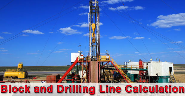
This article will focus on block and drilling line calculations as block efficiency, drilling power input/output, etc. Additionally, there are some examples which will help you understand how the formulas work.

Block-and-Drilling-Line-Calculation-cover-page

Block and drilling line efficiency formula is described below;

Block and Drilling Line Calculation 1

Power Output (Po) = Fh x Vtb

Power Output (Pi) = Ff x Vf

Block and Drilling Line Calculation 2

Where;

Fh is the hook load in lb.

Vtb is the velocity of the travelling block in feet per minute (fpm).

Ff is the fast line load in lb.

Vf is the velocity of the fast line in feet per minute (fpm).

The relationship between the fast line speed and the travelling block speed is listed below;

Vf = n x Vtb

Where;

n is number of lines strung between the travelling block and the crown block.

We can describe the hoisting efficiency into the following form.

Block and Drilling Line Calculation 3

Example#1: The maximum anticipated hook load is 500,000 and the travelling block velocity is 200 ft/minute. Hoisting efficiency is 85% and the drawworks efficiency is 75%. Based on the given information, what is the required horsepower for the drawworks for this situation?

Block and Drilling Line Calculation 4

Block and Drilling Line Calculation 5

Pi = 58,832,529 ft-lb/min

1 horsepower = 33,000 ft-lb/min

Pi = 58,832,529 ÷ 33,000 = 1,783 hp

We need to look at the drawworks. The drawworks output is the hoisting system output therefore we can figure out the horse power of the drawworks.

Pi = 2,377 hp

You need input horsepower of the drawworks of 2,377 hp.

Example#2: The string will be pulled out from 15,000 ft. The rig information is listed below;

Drilling lines: 12 lines

Hoisting efficiency: 70%

Drawworks: 1,200 hp

Drawworks efficiency: 80%

Expected hookload at 15,000 ft: 350,000 lb

What is the speed at which the first stand (90 ft stand) can be pulled out of hole based on the drawworks technical limit?

Block and Drilling Line Calculation 6

Ff = 41,667 lb

Fast line velocity (Vf) = Power Input (Pi) ÷ Fast line Load (Ff)

Power Input (Pi) comes from the drawworks and we can determine it from the drawworks efficiency.

Power Input (Pi) = 0.8 x 1,200 = 960 hp

1 horsepower = 33,000 ft-lb/min

Power Input (Pi) = 960 x 33,000 = 31,680,000 ft-lb/min

Fast line velocity (Vf) = 31,680,000 ÷ 41,667 = 760 fpm

Travelling block velocity can be calculated by the following equation.

Vf = n x Vtb

Vtb = Vf ÷ n

Vtb = 760÷ 12 = 63.3 fpm

The travelling block speed = 90 ÷ 63.3 = 1.42 minute.

The pulling speed for the first stand is 1.42 minutes.

Reference book => formulas-and-calculationFormulas and Calculations for Drilling Operations 

Free Cross Over Generator Excel Spreadsheet for Oilfield Use

$
0
0

You may have a problem regarding ordering the cross over to use on the rig because there are so many threads used for the operation. For example if you have just only three threads (3-1/2” IF, 4-1/2” IF, 7” BTC) for the operation. These are a total of 18 the possible crossovers that you may need as listed below.

3-1/2″ IF PIN X 4-1/2″ IF BOX

3-1/2″ IF PIN X 7″ BTC BOX

4-1/2″ IF PIN X 3-1/2″ IF BOX

4-1/2″ IF PIN X 7″ BTC BOX

7″ BTC PIN X 3-1/2″ IF BOX

7″ BTC PIN X 4-1/2″ IF BOX

3-1/2″ IF PIN X 3-1/2″ IF PIN

3-1/2″ IF PIN X 4-1/2″ IF PIN

3-1/2″ IF PIN X 7″ BTC PIN

4-1/2″ IF PIN X 4-1/2″ IF PIN

4-1/2″ IF PIN X 7″ BTC PIN

7″ BTC PIN X 7″ BTC PIN

3-1/2″ IF BOX X 3-1/2″ IF BOX

3-1/2″ IF BOX X 4-1/2″ IF BOX

3-1/2″ IF BOX X 7″ BTC BOX

4-1/2″ IF BOX X 4-1/2″ IF BOX

4-1/2″ IF BOX X 7″ BTC BOX

7″ BTC BOX X 7″ BTC BOX

You will get lost easily, won’t you??

confused

As you can see, it is quite tricky to determine all possible required cross over especially when you have a lot of connections. Therefore we create an Excel file to help you do this task. We call this file as “Cross Over Generator”.

facebook-show


What will this file help you?

It will help you generate all possible x-overs then you can identify which one you need or not. It will greatly reduce failure if you forget something.

Download the x-over generator file here ->http://goo.gl/CjDpZO

Then you open the file using Microsoft Excel. You will see the screen link this

Figure 1 - Open up

Figure 1 - Open up


First of all you need to enable Macro. You click “Enable Content” (Figure 2).

Figure 2 - Enable Content

Figure 2 – Enable Content

How To Use This file

This is the main page of this file (Figure 3).

Figure 3 - Main Page

Figure 3 – Main Page


You need to put the connection types in the blue cells only and you can input to 500 different connections (Figure 4 and Figure 5).

Figure 4 - Input Cells

Figure 4 – Input Cells

Let’s input some data into these cells.

4-1/2″ IF (NC 50)

3-1/2″ REG

9-5/8″ BTC

3-1/2″ FOX

4″ FH

4″ XT39

  Figure 5 - Input data

Figure 5 - Input data

Then you click “Generate X-over” (Figure 6)

Figure 6 - Generate Result

Figure 6 - Generate Result

Macro in the Excel file will generate all possible x-over like this (Figure 7).

 Figure 7 – x-over list generated

Figure 7 – x-over list generated


The cross-overs which are generated by this macro consist of three main types which are Box – Pin, Pin – Pin and Box – Box (Figure 8).

Figure 8 - Three main types of x-over

Figure 8 – Three main types of x-over


From the example above, you will get a total of 72 types of x-over.

Finally, you can select which one you need for operation from the list created by this file. We wish this file would help you to figure out the possible cross over needed for your operation. Please feel free to share with your friends : )

Ekofisk Bravo Blowout Oilfield Incidents

$
0
0

Ekofisk Bravo blowout incident happened when performing workover operation. If you study in the oilfield industry about well control incidents, there are several cases when the well was unable to control during workover operation. This is what personnel working in this industry needs to learn and fully aware of the hazard which could be occurred and this can affect lives, environment, etc. This is one of the reason why we always emphasize the important of well control in every operation.

The Ekofisk Bravo Platform Blowout

The Ekofisk Bravo Platform is located towards Ekofisk field’s north and is one of the two prime wellhead production facilities of Ekofisk. However, on April 22nd, 1977, it went through a major blowout which is regarded as the biggest oil spills till date at the North Sea.

Ekofisk Bravo 1

The Ekofisk B blowout took place when workover was being carried out at B-14 production well where they were busy pulling about 10,000 feet of production tubing. Before the task, the production Christmas tree valve stack was removed. Besides, the BOP was not installed. However, the well kicked and wrongly installed while the downhole safety valve failed, which caused immediate blow out of the well with wild release of gas & oil. However, fortunately the crew onboard was evacuated safely through lifeboats and was later transferred to the supply vessel. Miraculously, no one was injured.

This event led to wastage of approximately 28,000 barrel/day, later resulting into overall discharge of 202,380 bbls. Around 30-40% oil was assumed to be evaporated and the overall spill estimate by the Norwegian Petroleum Directorate was to be considered around 80,000 bbls & 126,000 bbls.

Ekofisk Bravo 2

Finally, after 7 days, the well was capped in April 30th, 1977. However, higher air temperature & rough seas helped the break-up of the most of the oil. Further investigations concluded that there was no major damage to the environment & shoreline pollution. Besides, there was no major damage to the platform.

The official inquiry later concluded that the blowout was the result of human error which later caused mechanical malfunction of safety valve. Such errors included were the faults in equipment identification, misjudgment, inappropriate planning & well control, and installation documentation. This blowout was regarded as the major blowout of the North Sea’s history as it was the very first North Sea oil spill. However, the ignition of gas & oil was prevented that led to no casualties and major injuries at the time of evacuation.

Additional Information about Ekofisk Field

Ekofisk is basically a block of oil field that belongs to Norwegian sector at North Sea located approximately 200 miles (320 Km) southwest of Stavanger. It was originally discovered by Phillips Petroleum Company in the year 1969 and is considered to be the foremost oil field of the North Sea. In fact, it was here when the oil was first discovered, after drilling more than 200 wells at North Sea that succeeds the discovery of Groningen gas field. In the year 1971, Phillips initiated to produce for the tankers directly from 4 subsea wells. However, today they plan to continue producing oil till 2050.

The Ekofisk reservoir comprises of Cod, West Ekofisk, Ekofisk, Tor, Eldfisk, Albuskjell, Edda & Embla oil fields. Besides this, the Ekofisk Center is an immense complex of structures & platforms that acts as a transportation hub for neighboring fields too, like Valhall, Gyda, Hod, Ula, Heimdal, Statfjord, Tommeliten & Gullfaks. The entire complex comprises of total 29 platforms. The oil that is produced is supplied through Norpipe oil pipeline to Teesside Refinery in the England. The natural gas is supplied through Norpipe gas pipeline to the Emden in Germany.

Ref: en.wikipedia.org/wiki/Ekofisk_oil_field

incidentnews.noaa.gov/incident/6237


Fracture Gradient Reduction Due to Water Depth

$
0
0

Fracture gradient is one of the critical information which drilling engineers need to know in order to design drilling programs. For the well control stand point, the fracture gradient directly affects on how much influx volume can be successfully contained in the wellbore. If the wellbore pressure is over the fracture pressure, formations would be broken down and this situation will result in loss of drilling fluid into formations. Additionally, it might lead to well control situation because of loss of hydrostatic pressure. Fracture gradient is quite straight forward for land operation because it will not be reduce due to water column. However, the fracture gradient will be reduced in deepwater environment. In this article, we will discuss why water depth can cause the reduction in fracture gradient.

Fracture Gradient Reduction Due to Water Depth

Basically, the fracture gradient is related to fluids occupying in pore spaces of rock and weight of rock which are called overburden pressure. Generally, the overburden of a typical sedimentary is about 1.0 psi/ft (19.2 ppg). Rocks will be fractured when the wellbore pressure exceeds the confining stresses acting on it. If we make a general assumption that the overburden pressure causes the minimum confining stress of the rock. Then the formation fracture gradient will not be 1.0 psi/ft if the location is offshore.

Note: this assumption is made in order to help you get more understanding on how and why water depth can decrease the formation fracture gradient.

Why does the water depth reduce fracture gradient?

Water has less density than rock and when it is calculated into overburden pressure, it will reduce overall overburden pressure. For the calculations in this article, we will use 1.0 psi/ft as the overburden of the rock.

Let’s take a look at the examples below;

1st Example – Comparison between land and offshore location at 4,000’ TVD.

Land operation at 4,000’ TVD (Figure 1)

reduce fracture gradient 1

Figure 1 – Land operation at 4,000’ TVD


Overburden at 4,000’ TVD = 4,000 x 1 = 4,000 psi

Convert 4,000 psi at 4,000’ TVD in to ppg = 4,000 ÷ (0.052 x 4,000) = 19.23 ppg

Offshore operation at 4,000’ TVD with a water depth of 2,000 ft (Figure 2)

Water density is 0.45 psi/ft.

reduce fracture gradient 2

Figure 2 – Offshore operation – 2000 ft water depth

 Overburden pressure = (0.45 x 2,000) + (1.0 x 2,000) = 2,900 psi

Convert 2,900 psi at 4000’ TVD in to ppg = 2,900 ÷ (0.052 x 4,000) = 13.94 ppg

From the first example, you will see that at 4,000’ TVD, water depth will reduce the overburden from 19.23 ppg to 13.94 ppg.

2nd  Example – Comparison between land and offshore location at 15,000’ TVD.

Land operation at 15,000’ TVD (Figure 3)

Overburden at 15,000’ TVD = 15,000 x 1 = 15,000 psi

Convert 15,000 psi at 15,000’ TVD in to ppg = 15,000 ÷ (0.052 x 15,000) = 19.23 ppg

reduce fracture gradient 3

Figure 3 – Land operation at 15,000’ TVD

Offshore operation at 15,000’ TVD with a water depth of 2,000 ft (Figure 4)

We will use the same water depth of 2,000 ft but the well depth is at 15,000’ TVD for offshore operation.

reduce fracture gradient 4

Figure 4 – Offshore operation at 15,000’ TVD

Overburden pressure = (0.45 x 2,000) + (1.0 x 13,000) = 13,900 psi

Convert 2,900 psi at 4000’ TVD in to ppg = 13,900 ÷ (0.052 x 15,000) = 17.82 ppg

As you can see in the second example, the overburden of the formation still decreases due to water depth. However, it has less effect than the shallow well.

Conclusion

Water depth will reduce the formation fracture pressure and offshore wells will have smaller margin between mud weight and fracture pressure than land wells because of water depth effect. At the same water depth, the fracture pressure at the shallower section will be decreased more than the deeper depth. What’s more, particularly at a shallow depth where the average overburden is greatly reduced by water column, more casing strings are required to reach the plan casing depth.

Reference books: Well Control Books

Can Women Work in the Oilfield (Oil and Gas Industry)?

$
0
0

Women nowadays are dominating the world of men especially when it comes to jobs. They work side by side with males in a man’s industry, which is considered as a great achievement. Back in the days, women should stay at home, serve her husband, cook for the family, care for the children and do the household chores. This happened for many decades until some brave ladies stood up and fought for women’s rights. They showed that women can do almost anything and they can perform the work of a man. In fact, there are women who work in the oilfield, which is a tough job. People, mostly men and unbelievably some women, don’t want to accept that Eve’s daughters can work hard and do laborious jobs too.

can-women-work-in-the-oilfield

Good thing these days men have embraced this fact and offer wider opportunities to the ladies. There are several male jobs that are now handled by women. These jobs include being a CEO, lawyer, doctor, rescuer, military work, police, a taxi driver, a construction worker, an electrician, a race car driver, engineer, oilfield worker and the list goes on. Some of these jobs were once performed by men and are not allowed for women.

If women can give a life to a human being which is the most difficult role among all, then they can do a man’s job too. Women are now allowed to work in a man’s industry because they are more flexible and hardworking. Companies hire women because they are easy to work with and they are good in everything they do. They give their best and provide so much dedication to whatever kind of work they are handling. In fact, some women can do an oilfield work which is literally quite a dirty job, but they can work hand in hand with men. Some may wonder about what would be their role in the oil and gas industry.

In the oil and gas industry, women play a huge and significant role. The oil and gas is a progressive and vast industry, so many opportunities are available for all especially to the ladies out there who are in need of a job and would want to work in an exciting and challenging industry. Women should also start to open their minds to try this kind of job as it offers a different and useful experience.

There are several office-based positions that women can do as engineer, geologist, geophysicist, IT support, engineering assistant, human resources, accountant, researchers, etc. Moreover, women can also work in the field as rig crew, field engineer, drilling supervisor, field inspector, wellsite geologist, etc. They can do excellent in their tasks like men do. Nowadays, oil and gas companies and service companies also increase woman workforces every year.

Being a part of a challenging and men dominated industry is not easy as it needs a lot of adjustment too. And it may be surrounded mostly by males, but as a woman, working in an oil and gas industry will offer more benefits. Aside from a good pay, you’ll meet new and different people from all walks of life. In this kind of work, camaraderie is also important because you work as a team and most of the jobs in the oil and gas industry is accomplished by a team. People work hand in hand, so if you are having difficulties in your task, you can always count on your teammates. Certainly, there are jobs in the oilfield that will match your skills and abilities. Finally, if you are a woman looking for oil and gas job, please don’t feel fear of anything. The oil and gas industry is always welcome.

You may need to read these articles also to get more ideas about working in the oilfield.

Useful E-book from Drilling Formulas Team


Introduction To Underbalanced Drilling VDO Training

$
0
0

Underbalanced drilling becomes very famous in several places of the world because there are some advantages over normal drilling operations. Today we would like to share the basic underbalanced drilling 101 for everybody who is interested in this topic. It is presented by Shell and we also add full VDO transcript for anybody who cannot catch the information from this presentation.

Underbalanced Drilling 101 Full VDO Transcript
underbalanced-drilling-101

This presentation introduces the concept and equipment used in underbalanced drilling operations. The key differences between underbalanced drilling and conventional overbalanced drilling are at both the conceptual and the technical level. At the conceptual level the subsurface drilling conditions needs to be investigated further, the rotating drill bit cuts away rock to deepen the well. The drill cuttings are lifted to the surface by the circulating drilling fluid.

In conventional overbalanced drilling operations, the hydrostatic pressure exerted by the drilling fluid in the well is designed to exceed the pressure of the hydrocarbon fluids in the reservoir. Since the pressure in the hole is higher than the pressure in the rock fluid therefore drilling fluid can lose into the formation. These losses cause damage to the near well-wall area resulting in reduced production, experience show that even a short exposure to overbalanced conditions can severely impair the productivity of the well.

In underbalanced drilling operations, the hydrostatic head of the drilling fluid is designed to be less than the reservoir pressure. This means that there is a continuous flow of hydrocarbons into the well during the drilling process. Under this condition, no near well-wall damage occurs and the wells ultimate production is not impaired. The privation of well-wall damage has several advantages; near well-wall damage prevention is just one of the benefits of underbalanced drilling. Another benefit of underbalanced drilling is the reduction of drilling problems such as differential sticking and drilling fluid losses. Producing the well while drilling increases reservoir knowledge, with this knowledge wells can be steered into more productive zones.

Reservoir pressure and depth determine the required density of the drilling fluid system, unlike conventional drilling which is limited to simple fluid systems, underbalanced drilling uses a variety of fluids to control bottom hole pressure at the high end of the density scale light fluids such as water syntactic based oils, natural crude oil or diesel form the drilling fluid.

To achieve lower bottom hole pressures a two phase flow system can be employed. This system consists of a light fluid aerated with a gas such as nitrogen or natural gas. First systems generally consist of water and surfactant. At the low end of the scale, mist or air based systems can be employed. Each of these fluid systems requires a different surface setup in what follows the commonly used two phase flow system is shown as an example to illustrate the technical differences between underbalanced and conventional overbalanced drilling.

A two phase flow system setup consists of the following elements, the light drilling fluid is stored in the rigs mud tank system and is pumped to the well by the rig fluid pumps lifting gas, in this example nitrogen, is injected into the fluid stream. Depending on the quantity of nitrogen needed. The source of the gas can be cryogenic tanks or a membrane unit that separates nitrogen from the air. The two phase fluid stream is injected into the drill stream using the conventional rig systems. The two phase fluid exit the base of the bottom of the hole carrying drill cuttings up the annulus. Since the hole is drill underbalanced reservoir fluid such as oil or gas are produced from the reservoir and mingled with the two phase fluid moving up the annulus, this means that the well is producing while being drilled. The returned fluid from the well is diverted by a rotating control head to the surface separation equipment.

The control head seals around the drill pipe while allowing the pipe to move in and out of the well and rotate. In some cases a snubbing unit needs to be installed to allow movement of the drill pipe in and out of the well under pressure. Moving slips on the snubbing unit grip the pipe and push or pull it against the upward force in a controlled manner. Flow from the well is controlled by a choke manifold and the processed in a full phased separation system, this system separates the returns into its constituency, light fluid, crude oil, nitrogen and natural gas and rock cuttings. The separated cuttings are collected for the disposal. The separators hydrocarbons are sent on the production facility flare. The light fluid is pumped back to the rigs mud system for treatment and reuse. This completes the tour of the main surface systems that are used in two phased underbalanced drilling operations.

In summary underbalanced drilling allows the well to product during the drilling phase. Underbalanced drilling operations require additional surface equipment and a careful upfront design. When applied in appropriate wells underbalanced drilling prevents formation damage reduces drilling problem and increases reservoir knowledge.


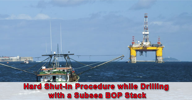
Hard Shut-In Procedure while Drilling with a Subsea BOP Stack

$
0
0

Nowadays, deepwater drilling is one of the important parts of drilling in the world and there are a lot of ongoing deepwater operations. Our team will start focus on subsea well control and this topic is about hard shut in procedure while drilling with a subsea stack. This is quite similar to surface stack but it is quite tricky how you space out the well properly because the BOP is way down below approximately thousand feet from sea surface.

Shut-In Procedure while Drilling with a Subsea BOP Stack

There are 3 steps which are space out, shut down and shut in and the details for the procedure are below.

1st step: Space Out

  • Stop drilling, pick up off bottom and space out to ensure that the tool joint will not be located across the BOP. Personnel need to pre calculate where to space out because the position on the rig floor will affect where the tool joint down hole.

2nd step: Space shut down

  • Shut down pumps

3rd step: Shut-in the well

  • Shut the well in on the top most BOP as annular preventer first and then open the upper choke valve against a fully closed choke manifold valve.
  • Confirm well is properly shut in and double check line up.  Check the accumulator unit to ensure that there is no leakage after closure of the BOP.
  • Inform rig supervisors and start record data as pit gain, Shut In Casing Pressure, Shut In Drill Pipe Pressure.

Reference books: Well Control Books

Enchova Central Blowout Oilfield Disaster

$
0
0

Learning from the past oilfield disaster will help you realize about well control, safety management, etc which you can apply to mitigate the future catasrophe. Today, we would like to share the information about Enchova Central which blown out years ago. This is very good information for everybody.

The Enchova Central platform, which was the place where two big catastrophies occurred was situated in the Campos Basin close to Rio de Janeiro and was administered by Petrobras. The initial incident was on August 16, 1984, when there was fire and an explosion. Most of the people and personnel at the time of the incident were saved with a helicopter or lifeboat. However, 42 workers lost their life in this catastrophe.

It was the most consequential and grave occurrence when there was an issue in the functioning of the lowering mechanism of a lifeboat due to which there was a malfunction with the bow hook. Consequently, the lifeboat was left hanging vertically till there was a rupture in the stern support and following this the lifeboat drowned 10 to 20m to the sea, which resulted in the death of 36 personnel. Around 6 personnel lost their lives on trying to jump 30 or 40m from the platform to the sea.

The next catastrophe took place about 4 years after the first incident on April 24, 1988, which caused havoc and completely wrecked the platform. When the well was being converted from oil to gas, there was an explosion. The BOP failed to shut in the well and all the efforts of destruction of the well were unsuccessful. At the time of the explosion and fire, drillpipe was forcibly extracted from the well and it hit a platform leg which triggered ignition of gas from the blast. The fire on platform then charred and burned for about a month and this caused substantial blow to the topside structure. A floating hotel was right adjacent to the Enchova Central, luckily during the explosion and hence there were no casualties and a safe evacuation. Following this incident, the platform was 100% rendered futile and there was a major loss. Then, there was a new facility for the purpose of restoring the place and the function was successfully rendered in a year and a half.

Shut-In Procedure while Tripping with a Subsea BOP Stack

$
0
0

After we publish this article “Hard Shut-In Procedure while Drilling with a Subsea BOP Stack”, there are some people asking us about what about the shut-in procedure while tripping with a subsea stack. So today we will focus on this topic.

 shut-In-Procedure-while-Tripping-with-a-Subsea-BOP-Stack

For the shutting in procedure with subsea stack, there are 3 steps which are stab valve, space out, and shut in and the details for the procedure are below.

 1st step: stab valve

  • Stab the full opening safety valve into the string and then make it up to the drillstring. Close the valve.

2nd step: space out

  • Space out to ensure that the tool joint will not be located across the BOP. Personnel need to pre calculate where to space out because the position on the rig floor will affect where the tool joint down hole.

3rd step: Shut-in the well

  • Shut the well in on the top most BOP as annular preventer first and then open the upper choke valve against a fully closed choke manifold valve.
  • Confirm well is properly shut in and double check line up.  Check the accumulator unit to ensure that there is no leakage after closure of the BOP.
  • Inform rig supervisors.
  • Prepare to strip back to the bottom.

Reference books: Well Control Books

Driller’s Method or Wait and Weight Method – What is The Practical Well Control Method for You?

$
0
0

Driller’s method and wait and weight method (engineer’s method) are widely used to circulate wellbore influx while maintaining bottom hole pressure constant. There are a lot of opinions regarding which method is the best for well control operation therefore this article will discuss about pros and cons of both methods.

driller-or-wait-and-weight-method

Driller’s Method

The driller’s method requires two circulations to kill the well. The first circulation is to circulate influx out of the well with original mud weight. The second circulation is to kill the well with kill weight fluid. During the first circulation, the bottom hole pressure remains constant due to maintain drill pipe pressure constant while circulating. For the second circulation, in order to maintain constant bottom hole pressure, casing pressure is held constant while circulating kill mud to the bit. Once the kill mud passes the bit, the drill pipe pressure will be held constant until the kill weight mud is on surface and there is no sign of influx in the annulus.

Wait and Weight Method

The Wait and Weight method requires only one circulation. The influx will be circulated out while the kill weight mud is displaced into the well simultaneously. While pumping the kill fluid from surface to the bit, drill pipe pressure schedule must be strictly followed. After that the drill pipe pressure is maintained constant until the kill mud returns back to surface.  Some people call the Wait and Weight method as “Engineer’s Method” because there are more calculations compared to the Driller’s method.

Comparison between Driller’s Method and Wait and Weight Method

Wellbore Problems While Killing the Well

In many places, wellbore instability is one of major wellbore issues. If the drill string is kept in a static condition for a period of time, the pipe can get stuck easily. For this situation, the Driller’s method will give you a better chance to successfully kill the well and minimizing wellbore collapses and pack off than Wait and Weight.

For W&W method, kill weight mud must be prepared prior to circulation therefore the drill string is in static condition with no circulation for a while. There is high chance for wellbore to collapse and pack the drillstring.

Casing Shoe Pressure

Shoe will be exerted the maximum pressure when top of gas kick is at the casing shoe. Once the gas pass the shoe, the shoe pressure will remain constant. The W&W can reduce shoe pressure when the kill weight mud goes into the annulus before the top of gas arrives at shoe. If you have larger drillstring volume than annular volume, you will not be able to lower the shoe pressure using Wait and Weight method. However, if time to prepare the kill weight mud is very long, gas migration will increase shoe pressure. There will be a possibility that using W&W can create more shoe pressure due to gas migration while preparation of drilling mud.

Nowadays, oil-based drilling fluid is widely used for drilling operation. Gas will be soluble in oil based mud and it will not be able to detect at the bottom. Gas may expand when it moves almost to the surface and it is often above the shoe. Hence, W&W will not help reduce shoe pressure.

Capability of Fluid Mixing System

Around the world, there are a lot of drilling rigs which don’t have great capability to mix drilling fluid effectively, therefore, kill weight mud cannot not be mixed as quickly as the operation required for killing the well using W&W. The Driller’s Method will not have this issue because the circulation can be performed right away. Waiting for preparing kill weight mud for a long time can lead to increasing in shoe and surface pressure due to migration of gas.

Well Control Complications when Bit Nozzles Plugged

If the bit nozzles are plugged during the first circulation of Driller’s method, drill pipe pressure is allowed to increase temporary by maintaining casing pressure constant until the drill pipe pressure stabilizes and then the new circulating pressure. During the second circulation of Driller’s method, if the plugged nozzles are encountered, casing pressure must maintain until the kill mud to the bit and then change to hold drill pipe pressure shown on the gauge.

While killing the well using W&W method, if the bit nozzles are plugged, the drill pipe schedule must be recalculated as soon as possible. If the new pressure schedule is not properly determined, the well can be unintentionally underbalance resulting more serious in well control situation. The situation will be more complex, if the well is highly deviated with/without taper string because it is quite tricky to calculate.

Well Ballooning Issue

Well ballooning effect is a natural phenomenon occurring when formations take drilling mud when the pumps are on and the formations give the mud back when the pumps are off. When ballooning is observed, it must be treated as kick. If W&W is utilized to manage this issue at the beginning, the additional mud weight can increase complexity of wellbore ballooning situation. More mud weight can induce more mud losses and the situation will be worse. Since the Driller’s method does not require additional mud weight hence there is no increasing in wellbore pressure. Therefore, the ballooning situation will not become worse.

Hydrate in Deepwater

Deepwater condition is high-pressure and low-temperature conditions which are ideal case for hydrate. Therefore, there is a high chance of hydrate formation in choke/kill lines and BOP when gas influx is taken in a deepwater well. Driller’s method will minimize hydrate issue because the circulation is established as soon as possible. The mud is still warm and the hydrate issue can possibly be mitigated. Conversely, killing the well using wait and weight method requires longer time to shut in because the kill mud must be properly prepared prior to circulating. The static condition will make the mud cool and it is a favorable condition for hydrate formation due to decreasing in temperature of drilling fluid.

Time to Kill The Well

The Wait and Weight method requires only one circulation but the Driller’s method requires two circulations. In the real well control situation, you may need to circulate more than one circulation therefore W&W may just save a little bit rig time compared to the Driller’s method.

Hole Deviation and Tapered String

For the Wait and Weight method, the drill pipe schedule must be calculated. It is very simple to figure out the schedule if there is only one size of drill pipe and the wellbore is vertical. However, nowadays there is little chance that you will drill a simple well like that. The drill pipe pressure schedule becomes difficult and complex in complex wells with multiple size of pipe. Without computer program, it is very difficult to do hand calculations to determine the right schedule. This can lead into more problem while performing well control operation because the bottom hole pressure can be unintentionally over or under balance.

Conclusion

Driller’s method has more advantages than Wait and Weight method. It is a preferred way to kill the well for many operators. The calculation is simple and operation is easier for crew to follow on the rig. The Driller’s Method also can reduce operational issues which may happened in well control as wellbore collapse, hydrate, etc. This method will not shut in for a period of time therefore gas migration effect is minimal.  When the complication is observed, controlling the well using Driller’s method will not need any additional calculations but if the W&W is used, the new drill pipe pressure schedule must be properly recalculated.

W&W can achieve lower casing shoe and surface pressure in some situations; however, it has more complexity in calculations and operation Due to gas migration the well is shut in, there are several cases when W&W will not lower shoe pressure. Additionally, W&W can give you higher shoe pressure due to incorrect drill pipe pressure schedule.  If you take a kick in deepwater well, using W&W can increase chance of hydrating the BOP and choke line.

In our opinion, Driller’s method is better than Wait and Weight for well control.

What is your opinion?

Reference books: Well Control Books


Introduction To Well Control for Horizontal Wells

$
0
0

Currently, horizontal wells are widely drilled around the world because the production from the horizontal  wells is outperform normal vertical or deviated wells at the same location. The productivity of the well increases because of longer penetration into a pay zone and/or more intersection of reservoir fractures (see Figure 1) .

 Introduction To Well Control for Horizontal Wells 1

Figure 1: A normal well and a horizontal well

Well control for the horizontal wells has the same fundamental principle during the circulation of influx from the well.  There are some corrections which adjust for frictional pressure between true vertical depth and measure depth since the horizontal wells usually have very long depth in comparison to wellbore true vertical depth.

Introduction-To-Well-Control-for-Horizontal-Wells-cover

Driller’s method is a preferred method for horizontal well control because it does not require drill pipe pressure schedule. Personnel can start circulate the first circulation to remove kick and displace the well with kill weight fluid using the second circulation method. However, if Wait and Weight method is planned to used, personnel should use a well control kill sheet with horizontal well feature to simulate the profile. It is very difficult to determine drill pipe schedule because there are several factors associated with calculations as well bore profile, size of pipe, hole size, etc.

Performing the well control in the horizontal wells is similar to normal wells but you need to understand about the hydrostatic change when the gas kick moves from a horizontal section to a vertical section. This make casing pressure profile increase drastically when compared to vertical or deviated wells.

Kick detection in horizontal wells is quite similar to the detection in vertical and deviated wells. Personnel need to use three positive kick indicators (pit gain, flow when pump off and flow show increase) to determine the influx.  Typically, drilling horizontal well usually drills into one formation therefore without any change in drilling parameters you should not see any changes in ROP. Therefore, indications of change in formation as ROP, LWD, torque and drag are very helpful for early kick indication because the changes indicate that you are in new zone which may have difference in reservoir pressure.

In the horizontal hole section, it is very difficult to immediately detect the kick because the kick is at the same TVD level. You will notice the wellbore influx when it reaches the vertical part of the well. Additionally, if the kick is in the horizontal part, you will not see any change in casing pressure due to gas migration.  You will see drastically increase in casing pressure when the kick goes into the vertical part. Hence it is very critical that reliable measurement equipment on the rig is very critical for the horizontal well drilling. What’s more, personnel need to understand the physical changes of kick on each part on the well which we will discuss further in next topics.

Reference books: Well Control Books


Kick Scenarios in Horizontal Wells For Well Control

$
0
0

Drilling horizontal wells are always in the development phase and people know the geological area pretty well. Additionally, they can accurately determine reservoir pressure of the target sand for the horizontal candidate. Hence, drilling engineers can plan the well with less chance of being underbalance condition. However, there are several scenarios where the well control occurs in horizontal wells. We will need to understand what circumstances can create well control situations in the known well bore pressure like the horizontal wells.

 kick-Scenarios-in-Horizontal-Wells-cover

Swabbed Kick

The swab in the horizontal wells is similar to swabbing in normal well. Swabbing effect can occur when the pipe is pulled off bottom for making up connection or when tripping out of hole. High rate of swab entering into the well can happen if swabbing occurs when tripping out of the hole. The length of horizontal section will be exposed to the differential swab pressure. On the other hand, the swab will be small when the pipe is pulled off bottom for making connection. In this case, you may see several small gas behind the bit which will show on the surface later.

Figure 1 - Swabbed Kick

Figure 1 – Swabbed Kick

You can swab the kick in the horizontal section while moving the pipe but the well may not flow because the vertical height of mud column does not change. It means that you still have the same hydrostatic pressure. Additionally, gas in the horizontal section will migrate up to high side of the wellbore only. The well will start flow when the gas is moved into deviated and/or vertical section.


Secondary Kick

This is when you have induce the second kick into the wellbore because of poor bottom hole pressure control resulting in hydrostatic pressure in the wellbore less than formation pressure. This problem can be mitigated by ensuring that the correct procedures are performed.

Figure 2 - sencodary kick

Figure 2 – Secondary Kick


Penetrate into New Formation

The well control in the horizontal section can be occurred when the well is drilled into new virgin reservoir which the reservoir pressure is unknown. This is very important that the horizontal well path will not cross the fault into virgin reservoir. For this case, you will see the response like the vertical or deviated wells. The positive well control indicators (well flow with pump off, increase in flow, pit gain) can be observed for this kind of kick.  Once the well is shut in, you will see shut in casing pressure and drill pipe pressure. It is not difficult to detect this kick when compared to swabbed kick.

Another issue if you take this kick is underground cross flow from the virgin formation (higher pressure) to the lower pressure sand. If the cross flow happens, you will casing pressure raising up to a certain level and maintain. It indicates that kick is pushed into the lower pressure barrier zone. As you can see, taking a high pressure kick and flowing into the low pressure zone can create a lot of confusion  and the normal well control procedure may not applicable. What’s more, in order to stop cross flow, barite plug, LCM or heavy pill cannot be utilized effectively in the horizontal zone. Therefore, it is very important to design the well which will not intersect the new reservoir with higher pressure than the current reservoir.

Figure 3 - Penetrate into New Formation

Figure 3 – Penetrate into New Formation

Barite Sag in Horizontal Section

Barite sag is a situation when barite falls down to the low side and the lighter fluid moves up due to the differences in density. This becomes an issue especially in highly deviated or horizontal wells because when the lighter fluid is circulated into vertical section, it reduces the hydrostatic pressure. It might be lower enough to create an underbalance condition in which wellbore fluid will be able to move into the well. The longer static period, more chance to have the barite sag issue. In order to minimize this issue, driller’s method is recommended because the first circulation can start right away. If the wait and weight is used, the sag issue can be worse because the wait and weight takes longer time to prepare drilling fluid before circulation gets started.

Reference books: Well Control Books

Kick Prevention for Horizontal Wells

$
0
0

After we’ve learnt several topics in regard to horizontal well control, today we will talk about how to prevent well control situation both while drilling and while tripping. Since the horizon well control is quite tricky when compared to normal well control due to long reach horizontal section, the best way is to prevent it.

kick-prevention-for-horizontal-wells

How To Prevent Kick While Drilling (Horizontal Wells)

  • After drilling into a pay window, it might be a good idea to flow check in order to check if the mud weight is good for well control before drilling deeper into the zone.
  • Plan the horizontal section to penetrate only one known reservoir pressure. Minimize uncertainty of crossing the faults.
  • Most of the time, sand in horizontal well has good porosity therefore you might have a chance of losses. The mitigation plan must be in place to deal with this issue.
  • Minimize swabbing possibility by BHA design which has the clearances between hole and drilling tool as large as possible.
  • Don’t stop the pump while moving pip off bottom. This will prevent swabbing before making up connection.
  • Optimize hole cleaning by use proper mud property, flow rate and drilling practices. The well with less cutting bed will have fewer tendencies to swab the kick into the well.

How To Prevent Kick While Tripping in (Horizontal Wells)

  • Use a trip tank and a trip sheet to monitor well while tripping in/out.
  • Recommend to pump out of hole for the horizontal section. This will reduce a chance of swabbing the well in. Ensure consistency of mud weight while pumping out.
  • Pump out with rotation will minimize cutting build up issue. Once pump out of the horizontal section, you may need to circulate bottom up.
  • Trip in with proper speed in order to minimize surge issue. Too much surge pressure can fracture formation and it will result in loss of drilling fluid into the well.
  • Maximize number of trips for drilling the horizontal zones.

Reference books: Well Control Books

Drill string valves and IBOPs VDO Training

$
0
0

Drillstring valves and IBOPS are one of the most critical well control equipment on the rig. This VDO training will teach you about drillstring valves and iBOPs. After watching this, you will fully understand several of the valves and their applications. Additionally, we also have full VDO transcript to help anyone who are unable to fully understand the English speaking in the VDO. We wish you would enjoy watching it.

Full VDO Transcript

Drill-string-valves-and-IBOPs


Drill string valves stop fluid from flowing up the drill string often if the drill kicks with the bit off bottom. Formation fluids flow from the annulus and up the drill string. Crewmembers close of the drill string valves. The flow is in the string, If the Kelly is made up the can close the upper or lower Kelly cock. If the Kelly is not made up then they can install the full opening safety valve in the top of the drill string.

An inside blowout preventer or IBOP is a one-way valve, a check valve that they can install in the drill string. One type of IBOP is a float valve that is sometimes made up in the drill string near the bit. It prevents backflow up the drill string.

Another type of IBOP is the drop in valve or D.I.V. It is dropped into the drill string and falls to a special landing sub that is usually located near to the top drill collar in the drill string. It allows the driller to pump mud down the string but the check valve will not allow influx fluid to flow up the string.

Another type of inside BOP is the heavy-duty check valve or a gray type valve named after the company that makes it. It is a plunger check that crew stab into the drill pipe at the surface. It is usually used during stripping operations.

Stripping is when the crew lowers the pipe into the hole while the BOPs are closed and under pressure. An upper Kelly cock is located above the Kelly. The upper Kelly cock usually serves as a backup to the lower Kelly cock. If the lower Kelly cock failed crewmembers would you was a specialize operating wrench to close the upper Kelly cock. The closed upper Kelly cock prevents further flow. It prevents the equipment above the Kelly from high pressure flow. Usually crewmembers close the lower Kelly cock if a kick puts risk on the equipment above the Kelly. They make it up at the bottom of the Kelly. A crew member uses a special operating wrench to close it. The crewmembers can also you was the lower Kelly cock to prevent a mud from falling out of the Kelly when they break off the Kelly to make a connection.

Here is a full opening safety valve. If the Kelly is not made up in the drill string and flow occurs, crewmembers can insert this safety valve into the drill string. This procedure is called stabbing.

A full opening valves has as large an inside opening as possible. When fully open flow from the drill pipe passes through the valve with no additional restriction. This relatively large opening allows the crew to stab the valve against pressure coming out of the drill string. The cruel picks up this safety valve by its lifting handles. They make sure it is fully opened and stab it into the drill pipe then they screw it into the pipe. Finally, the you was a special operating wrench to close the valve and shut off flow. Driller’s should make sure that valves have the right to cross over subs handy on the rig floor. Crewmembers should be able to make up the safety valve in any drill string member coming out of the Rotary. For example if a drill collar is in the Rotary, these safety valves threads may not match the drill collars threads. They will need the right cross over sub to make it work.

Float valves also prevent flow of the drill string. Crewmembers place a float valve in a string, a special drill string fitting just above the bit. One type allows mud to be pumped down but shuts against upward flow. Under normal conditions pump pressure moves drilling mud through the open one-way valve. An influx of formation fluids from below causes of the float valve to close. This prevents further flow of the drill string.

How To Get into Oil and Gas Industry

$
0
0

The standpoint for employment in the industry of oil and gas today has been consistently vehement.  Most people are expecting a “crew shift” transformation because today a lot of existing employees are quitting or retiring due to which there is substantial demand and fresh employment opportunities. The petroleum industry is one of the most wanted industries for employees because of challenge and payment. There has been increasing need for people who are skilled and credible, ranging through different genres from roustabouts, drilling supervisors, geologists, & engineers, health and environmental consultants, etc.  A couple of strong years of experience and consistency in the oil and gas industry could lead to brilliant opportunities and a bright future ahead. However, the question that arises is- “How should one go about it?

How-To-Get-into-Oil-and-Gas-Industry

Usually people can start their journey in this industry through technical or entry-level positions, which might need certain qualifications, but it is not mandatory.  It could be helpful to have some kind of knowledge or experience in mechanical or electrical knowledge because these skills can land you a job in oil & gas industry easier. Your resume will get better with safety-related or technical certifications. Apart from these, leadership & communication skills, working under pressure, being a perfectionist, team work and co-ordination are also required.

Offshore or Onshore?

Positions for both offshore & onshore are available; however, offshore jobs have better pay since individuals with more experience are chosen for the offshore jobs. In fact, offshore operations are quite expensive hence safe & efficient operations are crucial. There are some who think of offshore jobs as more dangerous, and require workers to stay away from home for longer time. There’s no doubt that such kind of jobs involve more long hours of duty and more difficult task, but when it comes to pay, it’s worth it.

Technical Knowledge – Do You Really Need It?

It would be helpful to give importance to your education for long term benefits because the people who succeed the most in this industry are college & technical school graduates in technical & professional positions.

You can opt for a 24-month degree course in technical degrees as mechanical and electrical technology, construction management, welding, etc, and further direct technical or mechanical experience will add to your resume. A degree from a good institute can help build your career options.

If you are a graduate and have a bachelor in engineering or science degree, it will present you to various better and high opportunities in your oilfield career. A bachelor’s degree in engineering could be advisable because the skills of an engineer are always needed in this industry.  A degree in Civil, Petroleum, Mechanical, Chemical or Electrical Engineering or in Geophysics or Geology would be really helpful for your career.

What Positions Are Available If I Don’t Have a Technical Background? 

If you don’t have a college degree, you still have several opportunities for radio operators, field hands, rig crew, heavy machinery operators, welders, roustabouts, drivers, cooks etc. Besides, most of the companies give training after hiring. You still can move up the ladder even though you don’t have the technical background. After you joint the company, if you work hard, your work and your experience will help you in the future career.

Experience and Network

Along with good education and good work experience, you need to have good networking skills to succeed in this industry. Very often there are opportunities which aren’t brought to people’s notice enough, so aspiring candidates are not aware of potential opportunities. So you need to network, talk to professionals, friends, and mentors in the industry as well as local & national professional organizations.

Service Companies Are Also a Good Choice to Work in The Oilfield

More often than not, it is easier to get an opportunity at a service company, as compared to the big companies like Chevron or ExxonMobil.  Service companies (Schlumberger, Halliburton, Baker, Weatherford, etc) usually provide ample positions for various operators and they also indulge in lot of research and development work. More often than not, you will come across news of companies merging, growing or hiring. You should keep the option of working anywhere outside your hometown open, which means, you should be willing to relocate if you have to. Usually, opportunities available would be in places which deal in extraction of oil and gas, like Texas, Oklahoma, Louisiana, Alaska, & North Dakota. There are ample great opportunities available to develop and nurture a career in this industry.

Additional Resources To Help You To Get into Oil and Gas Industry

Viewing all 497 articles
Browse latest View live


<script src="https://jsc.adskeeper.com/r/s/rssing.com.1596347.js" async> </script>