Quantcast
Channel: Drilling Formulas and Drilling Calculations
Viewing all 497 articles
Browse latest View live

Behavior of Gas in a Horizontal Well Kick

$
0
0

Gas kick behavior in horizontal wells is different from the gas behavior in normal wells (vertical and deviated wells). Gas follows Boyle’s gas law when it moves up to the shallower section of the wellbore. However, in the horizontal section, there is no change in volume because gas will move up to high side of the wellbore and there is no change in pressure.

behaviors-of-Gas-in-a-Horizontal-Well-Kick-cover

The gas kick volume will increase when the kick is circulated out of the horizontal section because the reduction in hydrostatic pressure results in expanding of gas as per Boyle’s gas law (see below).

Boyle’s Law

P1 x V1 = P2 x V2

You will not see any drastic pit gain when the gas kick is still in the horizontal zone but the pit gain will significantly increase once it starts going into the deviated / vertical section of the well (see Figure 1).

Figure 1 - Gas expands in the vertical section
Figure 1 – Gas expands in the vertical section

­­­

What are Responses of Shut In Drill Pipe Pressure and Shut In Casing Pressure in Horizontal Wells?

In horizontal wells, kicks can come into the well and you will see pit gain but when the well is shut in you will not see any difference between shut in casing pressure and shut in drill pipe pressure. This situation happens because the kick in the horizontal section does not have the vertical height (see Figure 2).

Figure 2 - SIDPP and SICP when gas kick is in the horizontal section

Figure 2 – SIDPP and SICP when gas kick is in the horizontal section

When compared to normal well, you should see the difference between these two pressure gauges because height of gas kick will reduce hydrostatic pressure in the annulus( see Figure 3).

Figure 3 - SIDPP and SICP when gas kick is in a normal well.

Figure 3 – SIDPP and SICP when gas kick is in a normal well.

Gas kick from swabbing effect in the horizontal sand may not be able to clearly detect even though the large kick is taken into the wellbore.

As you can see, it is very tricky to deal the gas kick at the beginning because the elevation of the horizontal section does not change. You may not know if the well takes kick until the gas is out of the horizon plan. The best way is to mitigate the possibility of taking a kick by good drilling practices and wellbore planning. You can see more details in this article “Kick Prevention for Horizontal Wells” which will go into details on how to prevent the well control in the horizontal wells.

Reference books: Well Control Books


Abnormal Pressure Caused By Faulting

$
0
0

Fault is a discontinuity in a geological structure and it sometimes can create abnormal pressure. Hence, you need to really understand how the geological fault can cause higher pressure even though it comes from the same reservoir.

abnormal-pressure-by-faulting

There are three fault types which are as follows;

  • Strike-slip, where the offset is predominately horizontal, parallel to the fault plane.
  • Dip-slip, offset is predominately vertical and/or perpendicular to the fault plane.
  • Oblique-slip, combining significant strike and dip slip.

Only dip-slip and oblique-slip can cause the abnormal pressure because there are some changes in elevation of the reservoir.

The illustration (Figure 1) below will demonstrate you how the fault can affect your mud weight required to drill the well. The reservoir has the same formation pressure of 6,500 psi. As time goes by, the earth movement causes fault in the reservoir. One reservoir is uplifted 1,000 ft TVD apart. The pressure is abnormal for that depth.

 23 Abnormal Pressure Due To Faulting 1

 Figure 1 - Uplift fault

We will calculate the equivalent mud weight at each depth in order to see the difference.

Location A: Equivalent Mud Weight = 6,500 ÷ (0.052 x 9,000) = 13.9 ppg

Location B: Equivalent Mud Weight = 6,500 ÷ (0.052 x 10,000) = 12.5 ppg

The well at “B” location can be successfully drilled with 13.0 pgg without any well control situation but you cannot use the same mud weight to drill the well at “A” location even though it is the same formation pressure. You may need mud weight more than 13.9 ppg to drill for the location “A”.

Finally, this abnormal pressure by faulting can create well control situation even though you know that you drill into the same reservoir. It is very critical to determine the elevation chance due to faulting to get the accurate equivalent mud weight in order to prevent the well control situation.

Reference books: Well Control Books

Adriatic IV Blowout and Platform Burning

$
0
0

Adriatic IV Blowout incident is one of the worst oilfield incidents happened in our industry. We need to learn and understand about it so we can prevent this incident to reoccur again in the future.

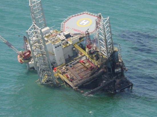
In the month of August 2004, Adriatic IV was placed near the Temsah gas production platform, off Port Said situated in Egypt (Mediterranean). The rig was busy drilling a natural gas well and there was a gas explosion which took place. It has been vindicated through reports that the blast was followed by a fire which later escalated to the Petrobel-run platform where it was raging persistently for about 7 days after which it was taken care of. About 150 personnel on the jack-up were saved and all the production and functions were stopped.

It was vindicated through studies and reports by Global Santa Fe that the Adriatic IV was completely submerged and could not be saved or restored. Joint owners of the platform were Italy’s ENI, BP & Egypt’s General Petroleum Corporation and the platform was completely in a dilapidated condition and hence the Egyptian Petroleum minister commanded to destroy it completely. In about 12 months following the catastrophe, the Temsah field and its production activities were restored in a full-fledged manner.

Always ensure that SIMOP’s are properly conducted.

Ref: Rigzone

What You Need To Know About Drilling Bit Balling Up and How To Troubleshooting It

$
0
0

Bit balling is one of the drilling operational issues which can happen anytime while drilling. This issue can cause several problems such as reduction in rate of penetration and surface torque, increase in stand pipe pressure. Personnel may eventually need to pull out of hole the BHA in order to clear the balling issue at the bit. This article will teach you about the bit balling and how to prevent it in the planning phase and how to effective detect and clear the balled up bit before it becomes a worse problem.

bit-balled-up

How You Recognize the Bit Balled Up While Drilling

Drilling Torque – Drilling torque will be lower than normal drilling torque since most of the cutters are covered up by cuttings.

Rate of Penetration – The ROP will decrease more than projection. If you drill 100 fph and later on the ROP drops to 50 fph without any drilling parameters changed, this might be this problem.

Standpipe Pressure – Standpipe pressure increases with no changes in flow rates or drilling parameters. Balling up around the bit reduce annular flowing area resulting in increasing pressure.

Factors Affecting Drill Bit Balling Up

Formation – Clay stone and shale has tendency to ball up the bit even though you use highly inhibitive water based mud or oil based mud.

Weight On Bit – High weight on bit will have more chance to create this issue.

Hydrostatic Pressure in Wellbore – High hydrostatic pressure (pressure above 5,000 psi) can induce bit balling issue in water based mud.

Bit Design – Poor bit cutting structure and poor junk slot area in PCD bits contribute to this issue.

Hydraulic – Low flow rate will not be able to clean the cutting around the bit.

Planning To Mitigate The Problem

Bit Selection – For the rock bits, steel tooth bits are better than insert bits because the steel tooth ones have greater teeth intermesh. For the PCD bits, the larger junk slot area is preferred.

Bit Nozzle Selection – The bits with high flow tube or extended nozzles are not recommended. If the bigger bit size is utilized, don’t block off the center jet. The center jet will flush all cutting more effectively.

Good Hydraulic – Hydraulic horse power per cross sectional area of the bit is the figure which can be utilized for measuring good hydraulic for bit balling mitigation. Hydraulic horse power per square inch (HSI) less than 1.0 will not be able to clean the bits. It is good practice to have more than 2.5 of HSI for good bit cleaning.

Weight On Bit – Don’t try to run a lot of WOB. If you increase WOB but you get lower ROP, you may have bit balling up issue. You should lower the weight and attempt to clean the bit as soon as possible.

Drilling Fluid– Mud chemical additives as PHPA which can prevent clay swelling issue must be added into the water based mud system. If feasible, drilling with oil based fluid will have less chance of balling up bit/BHA.

What Should We Do if The Bit Balling Is Occurred?

Stop drilling and pick up off bottom – if the drilling operation keeps continue, it will make the situation even worse. It is a good practice to stop and pick up off bottom to fix the issue quickly.

Increase RPM and Flow Rate – Increasing RPM will spin the cutting around the bit more. Additionally, increase flow rate to the maximum allowable rate will help clean the bit.

Monitor pressure – if you see decreasing in stand pipe pressure to where it was before, it indicates that some of cuttings are removed from the bit.

Lower WOB – Drill with lower weight on bit.

Pump high vis pill – Pumping high viscosity pill may help pushing out the cutting.

Drill Bits VDO Training

$
0
0

Drilling bits are one of the key tools to achieve good performance drilling and there are several types of bits. Therefore, personnel need to understand in order to use the right bits for the task. Today, we would like to share this excellent VDO teaching you about drilling bits. This VDO is excellent for everybody because it has a lot of illustrations and animations along with full explanations. As usual, we have full VDO transcript for anyone who cannot catch the wording from this footage.

VDO Transcript

drilling-bit

As we discussed in the last section, crew members install the bit on the on the bottom drill collar. Two kinds of bits are roller cone bits and fixed cutter bits. Fixed cutter bits are also called fixed head bits. Roller cone bits usually have three cone shaped devices with teeth or cutters. As the bit rotates the cone and cutters rotate to drill a head. Fixed head bits also have cutters but manufacturers embed them in the bit’s head. The bit’s head moves only when the bit rotates. It has no moving parts like the cones on a roller cone bit. Both roller cone bits and fixed head bits come in sizes ranging from 2 or 3 inches or about 50 – 75 millimeters in diameter to more than 36 inches about 1 m in diameter.

Two basic kinds of roller cone bits are available. One has steel teeth and the other has Tungsten Carbide inserts. On a still tool bit also called a middle tool bit, the manufacturer mills or forges the teeth out of the steel that makes up the cone. Steel tooth bits are the least expensive bits. When used properly they can make hole for many hours.

Manufacturers design steel tooth bits to drill soft, medium or hard formations. With Tungsten Carbide inserts the manufacturer presses very hard Tungsten buttons or insert into holes drilled into the bit’s cones. Tungsten Carbide is a very hard metal. Tungsten Carbide inserts insert bits cost more that steel tooth bits. However, they usually last longer because Tungsten Carbide is more resistant to wear than steel. In general Tungsten Carbide inserts bits drill medium to extremely hard formations but can also drill soft formations. Soft formation bits usually drill best with a moderate amount of weight and high road way speeds. Hard formation bits on the other hand usually drills best with high weight and moderate rotary speeds.

Three types of fixed cutter bits are available: Polycrystal and diamond compact or PDC bits, diamond bits and core bits. This PDC bit has cutters made from man-made diamond crystals and Tungsten Carbide inserts. Each diamond and Tungsten Carbide inserts cutter is called a compact. Manufacturers place the compacts in the head of the bits. As the bits rotate over the rock the compact shears it. PDC bits are very expensive. However, when used properly they can drilled soft, medium or hard formations for several hours without failing. A compact PDC layer is very strong and wear resistant. Manufacturers bond the diamond crystals to the Tungsten Carbide inserts backing under high pressure and temperature. The Tungsten Carbide backing, gives the compact high impact strength. It also reinforces the wear resistant properties of the cutters.

Manufacturers make diamond bits from industrial diamonds. But diamonds are the bits cutters. Diamonds are one of the hardest substances. A diamond bit breaks down the rock during drilling by either compressing it shearing it or grinding it as shown in this animation. Here, the diamond is acting like sand paper wearing the rock away. They embed the diamonds into the metal matrix that makes up the head of the bit. Diamond bits are expensive. When properly used however, diamond bits can drill for many many hours without failing.

Crew member run a core bit and barrel when a geologist wants a core sample of the formation being drilled. A core bit is normally a fixed head PDC or diamond bit. It has a hole in the middle. This opening allows the bit to cut the core. Diamonds or PDCs line the opening and sides of the bit. The ring crew fits the core to a core barrel. The core barrel is a special tube usually about thirty to ninety feet or nine to twenty-seven meters long. They run the core barrel at the bottom of the drill string, it collects the core, cut by the core bit. Cores allow geologists to take a look at a actual sample of the formations rock. From the sample, they can also tell whether the well will be productive

Mud Gas Separator (Poor Boy Degasser) Plays A Vital Role in Well Control Situation

$
0
0

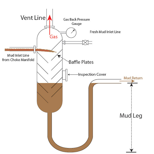
Mud gas separator located at downstream of the choke manifold is one of the important well control equipment that you need to focus. It separates gas out of the mud after the gas comes out of hole. Gas will be vent to atmosphere via the vent line in derrick (offshore operation) or the line away from the rigs (land operation) and the mud will be returned back to the pit. In the oilfield, people have several names for the mud gas separator as “poor boy degasser” or “gas buster”. While drilling, the mud gas separator should be lined up at all times and filled with the present mud weight currently used.

mud-gas-seperator

The concept of this equipment is density difference between liquid and gas. When the mud coming out from the choke manifold goes into the mud gas separator, mud will hit the baffle plates which are used to increase travelling time and allow gas to move out of the mud. Gas which has lower density than air will move up and mud will goes down due to gravity (see – Figure 1). Mud leg will provide hydrostatic pressure in order to prevent mud going through the separator into the rig.

mud-gas-seperator-1

Figure 1 - Mud Gas Separator Diagram

The mud gas separator is strictly used for well control only. There are some events that this equipment is utilized in a well testing operation. Additionally, inspection for the gas buster must be performed frequently the same as other well control equipment. People tends to forgot about this since it is just only a vertical separator tank without high pressure specification like BOP, choke manifold, valves, etc. Erosion is one of the worst enemies to the vessel like this and it can be seen at the points where the drilling mud impinges on the internal wall vessel.

Each mud gas separator has limitation on much it can safely handle volume of gas. If the volume of gas exceeds the maximum limit, gas can blow through into the rig. It is very important that you must estimate gas flow rate on surface based on pit gain and kill rate in order to see how much expected gas on surface. This will be the limitation on how much you can circulate for well killing operation. You can estimate the volume gas on surface by using well control kill sheet provided by several companies. You need to ensure that the vent line should be as straight as possible with a larger ID in order to minimize back pressure while venting the gas out.

The pressure gauge should be installed on the mud gas separator and frequently calibrated. This is very important because you will use this gauge to monitor the gas blow through situation. If the pressure in the vessel is more than hydrostatic pressure provided by mud leg, gas will blow through the vessel. By carefully monitoring, you will be able to react in a timely manner. If the pressure gauge shows you that pressure will be reach the limit, you should reduce current circulation rate to control volume of gas coming into it.

There are several considerations for mud gas separator design. You need to know the reservoir gas because if it is a sour gas (H2S), the mud gas separator should be able to handle this. The normal vessel will not work safely with H2S. Even though it has a name as “poor boy gasser”, it does not mean that it can be built in a cheaper way by some machine shops. The vessel must be fabricated to meet ASME specification and there must be a third party to certify it. What’s more, the scheduled preventive maintenance must be in place and strictly followed.

How Much Pressure Will Cause Blow Through?

This is a very important concept of blowing through while performing well control. Mud leg length is 20 ft and mud weight is 9.5 ppg (see – Figure 2)

mud-gas-seperator-2
Figure 2 - Mud Gas Separator and Blow Through

Pressure to blow through = Hydrostatic pressure provided by mud leg
Pressure to blow through = 0.052 x 9.5 x 20 = 9.88 psi

Reference books: Well Control Books

17 Mind-Blowing Oil Drilling Rig Photos – Get Inspired For Oilfield People

$
0
0

Many people works on the oil rigs both offshore and onshore operation and a lot of people may get bored with the rig. Therefore we would like to share some spectacular drilling rig images. There are various rig types as land rig, shallow water rig, offshore deepwater rig, etc at various environment. At least, we wish these photos would inspire you :)

Please feel free to share with your friends and colleagues.

Rig Image 2

Rig Image 1

Rig Image 3

Rig Image 4

Rig Image 5

Rig Image 6

Rig Image 7

Rig Image 8

Rig Image 9

Rig Image 10

Rig Image 11

Rig Image 12

Rig Image 13

Rig Image 14

Rig Image 15

Rig Image 16

Rig Image 17

All images are legally bought from Shutterstock.com, 123RF.com and Thinkstockphotos.com

More royalty free oilfield images from us - Royalty Free Oilfield Images

Know about Swabbing and Well Control

$
0
0

There are several situations when a kick is induced by swabbing effect. Today, we are going to discuss swabbing and well control situation. Swabbing is a condition when the string is pulled out of the well and it creates temporary bottom hole pressure reduction. If the hydrostatic pressure reduction is large enough to create underbalance condition, the well will eventually flow.

24-Know-abou-Swabbing-and-Well-Control-cover

When you swab the fluid in, the swabbed fluid may not necessarily cause pit gain or the well flowing because the volume swabbed in is not significant. However, if you have several swabbed-in fluid, the well will finally flow.

Figure 1 - Take Swabbed Kick

Figure 1 – Take Swabbed Kick

It is quite tricky to recognize the swabbing volume and the most trustable method to detect is by tracking hole fill volume. For example, if the volume displacement for 10 stands pulled is 8 bbl but the hole fill volume is just only 6 bbl, 2 bbls of kick may possibly be swabbed in while tripping out. Once the swabbing is detected, you need to trip back to the bottom and circulate bottom up even though the well is not flowing. If you don’t go back to the bottom, it will be very difficult to control the well off bottom once the swabbed gas moves up to shallower depth of the well.

In some situations, you may need to consider performing a short trip operation to determine the effect of bottom hole reduction by swabbing and loss of equivalent circulating density. The short trip becomes very critical when you drill into an unknown pressure zone. For this case, the result from the short trip will tell you whether you need to raise mud weight or not.

Factors that increase a chance of swabbing in are as listed below;

Balled up Bit and BHA The balled up bit/BHA acts like an excellent piston and this will cause greater swabbing effect. If the well is at near balance condition, the well will have more chance to be underbalance due to swabbing.

Formation pressure vs hydrostatic pressure If the hydrostatic pressure is equal to or slightly above formation pressure, the well can be swabbed in so easy.  In order to mitigate this issue, you need to have overbalance margin (trip margin) more than pressure reduction by swabbing.

Mud Properties – poor mud properties as high rheology, high viscosity, high gel strength, etc have high tendency to induce swab kick while pulling out. It is very critical to monitor the drilling fluid properties and personnel should have action plans to keep the mud in a good shape.

Pulling SpeedFaster tripping speed, higher chance to swab influx. It is very critical to monitor the well while pulling out and the pulling speed must not induce the well control situation.

Larger OD of Drilling Tools – Larger tools as fishing tool, coring tool, drill collar, mud motor, etc enhance swabbing tendency. Carefully tripping with larger tool is a key success to prevent the problem.

Swelling/Heaving Formations – Swelling and heaving formation will reduce wellbore diameter resulting a small clearance between an open hole and a BHA or a bit. While pulling out with a small clearance, it has higher chance to swab in the well.

How To Minimize Swabbing

There are several items which can minimize swabbing as listed below;

  • Keep the mud in good condition
  • Pull out of hole with reasonable speed
  • Add lubricant additives and maintain good drilling hydraulic to prevent bit/BHA balled up
  • Add chemical to prevent clay swelling in water based mud or use oil based mud drilling into clay formation
  • Pump out of hole instead of pulling out

Reference books: Well Control Books


Fatality Drilling Rig Accident, Oilfield Worker was Knocked 6 feet to the floor

$
0
0

This is the oilfield incident resulting in our friend working on the rig got killed. It is very important that we need to heavily focus on the safety. Every year, people get injured due to several causes while working in the oilfield. For this case, there are several contributing factors the high pressure, line of fire, equipment inspection, etc. We want you to work safely for yourself and your family.

 land-rig

A high-pressure gate valve that came off a leaky standpipe on a Cyclone rig north of Parachute early in the evening of Oct. 21 struck and killed Shane Hill, 34, of Grand Junction and blew his body 6 feet away from the valve, a state report says.
The rig was being operated for WPX Energy.

The accident report filed with the Colorado Oil and Gas Conservation Commission said that the rig’s day crew had tightened a leaking standpipe and fitted it with a new gasket. The day driller informed the night crew of the repair, but when the evening crew took over, the pipe began to leak again.
Operators decided to shut down and repair the leaking gasket. The crew began by attempting to dislodge a manifold to perform the repair. After several attempts to dislodge the manifold, the crew decided that removing a 2-inch fill-up flex line was necessary. Workers did that and replaced the gasket.
The manifold was put back in position and tightened. The rig manager gave the word for the driller to turn the pumps on and pressurize the system to allow the rig to resume drilling.

“Once the system was pressurized to 2,700 psi, the 2-inch high-pressure gate valve parted from the 2-inch high-pressure nipple on the standpipe, striking [Hill],” the report said.
Hill was struck on the back of the head, according to Garfield County deputy coroner Thomas Walton.

After the drilling fluid cleared, the crew reported finding Hill approximately 6 feet away from the valve. Efforts by crew members and emergency medical workers to revive him were unsuccessful, the report said.

Source: Post Independent


Trip Tank and Its Importance to Well Control

$
0
0

Trip tank is a small tank which has a capacity of 20 – 50 bbl and its shape is tall and shallow because it can effectively detect volume changes. The trip tank system has the ability to continuously fill the well and take return back to the tank. With this capability, it will keep the hole full all the time and the volume changes either increasing or decreasing can tell the condition of the well.

25-Trip-Tank-and-Its-Importance-on-Well-Control-cover

The diagram (Figure 1) below demonstrates how the trip tank is lined up.

25 Trip Tank and Its Importance on Well Control 1

Figure 1 – Trip Tank Line Up To Continuously Fill The Hole

Each trip tank has a pump which will suck the fluid from the tank and pump into the well via the fill up line connected to a bell nipple under the rig floor. The fluid return will flow back via a return line and back to the trip tank. The float in the trip tank is connected to the wire and the position of the float will represent the trip tank volume indicator. What’s more, nowadays several rigs have installed the electronic instrumentation for the accurate volume measurement. This will help personnel on the rig track what is going on the well very quickly and accurately. As you can see, the complete system allows personnel to monitor the well.
The trip tank must be maintained in order to avoid solid build up, pump and valve failure, leakage, etc. Moreover, it is very critical to frequently check the float and the electronic instrument to see if they are in good condition.
Stripping operation requires a separate trip tank which has very small capacity of 3 to 4 bbl therefore it is not recommended to use the normal trip tank for this operation. The small volume tank, called “strip tank”, has more accuracy and suite for the operation.

How The Trip Tank Monitor The Well For Well Control

Trip Out of Hole

While pulling out of hole, each stand of drillstring pulled out must have the same amount of drilling fluid to replace the drillstring volume. For instant, each stand should take around 0.8 bbl. If you pull 10 stands out of hole, you should see at least 8 bbl of mud volume decrease in the trip tank. If you see the volume displacement less than what it should be, it indicates that the well is swabbed in.

25 Trip Tank and Its Importance on Well Control 2

Figure 2 - Trip Tank While Tripping Out

Trip In Hole

While tripping in hole, mud will be pushed out of the well to the trip tank because steel displacement will replace the drilling fluid in the well. The volume displacement should be the same as the steel displacement. If the volume displacement is more than the steel displacement, the well may has some unwanted kick in the well.

25 Trip Tank and Its Importance on Well Control 3

Figure 3 - Trip Tank While Tripping In

Flow Check

While flow checking, the volume in the trip tank should be at the same level. There should not be any changes. Increasing volume in the trip tank means the well is flowing. Conversely, if the volume decreases, the well has static loss.

25 Trip Tank and Its Importance on Well Control 4

Figure 4 – Trip Tank While Flow Checking

Reference books: Well Control Books

Dull Bit Grading Handbook – Great for Your Reference

$
0
0

Dull bit grading is a standard method to grade the bit and it will also help personnel to understand bit performance better. However, it is sometimes very difficult to understand the meaning of the codes showing in the grading because you’ve never seen these dull characteristics before.   Especially, there are new people who start to work in the oilfield therefore it is very critical to have them learn the correct way to do the bit grading in a short period of time.

dull-bit-grading-handbook-cover

One of my friends shares this very useful dull bit grading created by Smith Bit company and I can say that this is an excellent book to help you grade the bit correctly.

Let’s take a look in this book what inside

Roller cone dull bit grading part

roller cone dull bit grading part

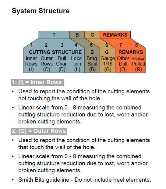
System Structure

system structure

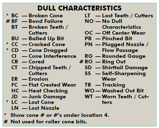
Dull Characteristics

Dull Characteristics

Images showing the dull characteristics of the bit – Every dull type has an image to show you how it looks like.  This part is extremely helpful for you.  This book also tells you causes of bit failure.

Images showing the dull characteristics

There is another part which is “Fixed Cutter Dull Grading”. This is applicable for PDC bits and diamond bits

 Fixed Cutter Dull Grading

Dull characteristics for fixed cutter bits

Dull characteristics for fixed cutter bits

Location on the bit structure

Location on the bit structure

Images demonstrate how it should look like for each dull characteristic of the fixed blade bit

 Images demonstrate dull characteristic of the fixed blade bit

 There is a lot of information from this book and you can download it from this link -> Dull Bit Grading Book

Please feel free to add any comments or suggest.  We wish this book would be advantage for you and your colleges.

Arabdrill 19 Collapse Incident

$
0
0

Expect for unexpected.  Arabdrill 19  incident is one of the oilfield disasters which you should learn from it. I would like to share you about this because it will help you learn from the past. It is such a very dangerous condition while working in the field because there are several unknown factors so we need to do the proper risk assessment, fully understand the task, follow the rule/procedure and don’t feel free to stop the task if it is unsafe. The detail below is about the Arabdrill 19.

Arabdrill 19 was made by Promet in Singapore on 1982, the AD19 was initially known as Sedneth 202 and it was under contract to Aramco working offshore Saudi. It was vindicated through studies and reports that the jack-up was situated over a production platform wherein it was apparent that a leg happened to buckle and get entangled which caused the breakdown of the AD19 on the platform. Although the information is not very clear, it is apparent that the catastrophe caused the platform’s production tree to be pruned off which triggered a blast and explosion followed by fire which resulted in the submersion of the jack-up as well as the platform.


The owner of the rig, Schlumberger stated that several people were injured in the catastrophe; however there were no reported deaths. Various other reports noted 3 casualties due to the explosion. The leading reason of the occurrence of the accident was the leg jabbing out through the seabed, and it was reported a 100% loss. Later, The AD19 was restored and held for resale by Rig Masters.

Dropped Top Drive and Travelling Block Incidents – Where Were They Happened?

$
0
0

My friend, Robert, forward my an email chain about dropped Top Drive and Travelling Block. It was scary and I felt deeply sorry for everybody. I would like to know where there were happened and their details because I just got only photos with few wordings. I want to learn about these incidents and to be able to share the right stories to my colleagues so we can have the safe workplace while working on the rig. Each photo has the number assign. If you know each particular photo, please feel free to leave me some comments so I can share it later with the team.

1


2

3

1

4

2

5

3

6

4

7

5

8

6

9

7

Fatality Incident in Colorado- Fracking Accident Kills 1 Halliburton crew member and two were injured at Weld County Site, USA

$
0
0

My condolences to the Family regarding this bad incident (Fatality Incident in Colorado- Fracking Accident Kills 1 Halliburton crew member and two were injured at Weld County Site). We’ve seen a lot of catastrophic incident about the fracking job and we would like to emphasize everybody about the trapped pressure potential. This can happen very quickly. These are some NEWS on internet that we collect for everybody and we wish the industry would learn from the failure to make the safer work place.

Source: Denver Post

A high-pressure water line that had frozen overnight at a Weld County fracking site exploded early Thursday as workers tried to thaw it, officials said. One worker was killed and two were seriously injured.

The accident happened at an Anardarko Petroleum Corp. location near Mead during fracking operations run by Halliburton Co. It prompted Anadarko to suspend all fracking operations in the area as a safety measure.

Two other Halliburton employees were taken to Denver Health and Medical Center of the Rockies in Loveland.

“This is a very difficult time for all of us at Halliburton, and we are working with local authorities as they look into the details of this incident,” Halliburton said in a statement. “Our thoughts and prayers are with our employees’ loved ones. Out of respect for the families’ privacy, we are not releasing any additional information at this time.”

Weld County Sheriff’s Office deputies are investigating the accident. According to initial reports, the death and injuries were caused by a high-pressure water valve that ruptured, said agency spokesman Sean Standridge.

Firefighters are also on scene.

The incident occurred at 9:30 a.m. at a rig site off of Weld County Road 9½ just north of Colo. 66 near Mead.

The workers were trying to warm the pipe, which had frozen, when it ruptured, Standridge said. The temperature was about 10 degrees at the time, but overnight temperatures were well below zero.

The water pressure was estimated at between 2,500 and 3,500 pounds per square inch. Dozens of people work at the site, which is about two hundred yards long.
An Anadarko statement said Thursday’s accident “has left us all shaken and heartbroken. We have suspended all completions activities in the area and will cooperate fully with the authorities in their review.”

Federal investigators with the Occupational Safety & Health Administration in Denver were notified of the fatal accident at about 11:30 a.m. Thursday, said Herb Gibson, OSHA area director.

Two investigators are at the Mead area site looking into the accident, Gibson said.

“It’s a dangerous industry,” Gibson said. “This is a tragic situation.”

The OSHA investigation is in a preliminary stage, Gibson said, and he could not go into further details. The federal agency was contacted Thursday by local government officials, Gibson said.

In 2012, a 60-year-old worker died in another Weld County drilling accident that occurred when pressurized gas was released as workers prepared an Encana Corp. Davis well pad to begin pumping.

Source: ABC  NEWS

An accident at a hydraulic fracturing site in northern Colorado killed one worker and seriously injured two others Thursday, authorities said.

The three men were trying to heat a frozen high-pressure water line at the oil or gas well site when it ruptured, Weld County sheriff’s Sgt. Sean Standridge said. One man was hit by a stream of water and died from the impact.

The injured men — Thomas Sedlmayr, 48, and Grant Casey, 28 — were flown to hospitals. The name of the man who was killed was not released.

The accident happened near Mead, about 35 miles north of Denver, on the fourth straight day of frigid weather in the region.

“The pipe was frozen and they were trying to heat it up to get it flowing again,” Standridge said.

The temperature in the area was about zero degrees at the time of the accident, National Weather Service meteorologist Bob Kleyla said. Overnight, the temperature had dropped to minus 5, which is severe but not as cold as in other locations in Colorado such as Denver International Airport, where the low was minus 14.

The men were working for Halliburton Co., which Anadarko Petroleum Corp. contracted to perform fracking operations at the well. Fracking involves injecting high-pressure mixtures of water, sand or gravel, and chemicals into the ground to extract oil and gas from rock.

After the accident, Anadarko shut down all the fracking pads in the area as a safety precaution.

“This is a very difficult time for all of us at Halliburton, and we are working with local authorities as they look into the details of this incident,” Halliburton spokeswoman Chevalier Mayes said in a statement.

Three inspectors from the Occupational Health and Safety Administration were at the site investigating the cause of the accident and whether it could have been prevented, Area Director Herb Gibson said. He said there had been no prior fatalities at the Anadarko site.

“It’s definitely a dangerous industry,” Gibson said.

Learn about Maximum Surface Pressure in Well Control (MASP, MISICP and MAASP)

$
0
0

There are several terms/acronyms about maximum surface pressure in well control such as MASP, MISICP and MAASP. These terms sometimes confuses a lot of people hence this article will explain each term and demonstrate how to use it.

26-MASP-MISICP-MAASP-cover

Leak Off Test (LOT)

The first factor you need to understand is Leak of test pressure (LOT). LOT is the surface pressure that breaks down formation at a casing shoe for each section of the well.

Leak off test pressure formula is listed below;

Leak off test pressure, psi = Surface pressure to break formation, psi + Hydrostatic pressure, psi

Typically, leak off test pressure is describe in equivalent mud density term therefore the formulas will be like this

Leak off test pressure, ppg = (Surface pressure to break formation, psi ÷ 0.052 ÷ shoe TVD, ft) + Mud weight, ppg

Maximum Allowable Surface Pressure (MASP)

Maximum Allowable Surface Pressure (MASP) is based on surface equipment rating and most of the time, the MASP is determined by a percentage of the casing burst pressure. Generally, 80% is used for derating from the original casing burst pressure however it can be less than 80% if the well is very old and the casing is in very bad shape.

MASP, psi = percentage of casing burst x casing burst pressure, psi

Maximum Initial Shut-In Casing Pressure (MISICP)

Maximum Initial Shut-In Casing Pressure (MISICP) is the maximum casing pressure before fracturing the casing shoe when the well is shut due to well control. MISICP formula is listed below;

 MISICP, psi = (Leak Off Test pressure, ppg – current mud weight, ppg) x 0.052 x Casing shoe TVD, ft

Maximum Allowable Annular Surface Pressure (MAASP)

Maximum Allowable Annular Surface Pressure (MAASP) is the maximum annular pressure which will cause formation break down. MAASP can be in a static condition and a dynamic condition (circulating).

At the static condition, MAASP will be same as MISCIP and the equation is listed below;

MAASP, psi = (Leak Off Test pressure, ppg – current mud weight, ppg) x 0.052 x Casing shoe TVD, ft

At the dynamic condition, due to friction pressure in the annulus while circulating, it is very difficult to calculate an accurate MAASP therefore it is not recommended to determine the dynamic MAASP while circulating the kick out of the well. Furthermore, you should NOT use MASSP at the static condition while circulating. For example, you determine the static MASSP of 1000 psi and while circulating, casing pressure can go more than 1000 psi. If you try to lower the casing pressure down by misleading the interpretation of this value, the additional kick will go into the well and finally it will make the well control situation even worse.

Example: 9-5/8” casing was set at 8,500MD/8,000’TVD.

9-5/8” casing : L-40, 43.5 lb/ft, burst pressure = 6,330 psi, collapse pressure =3,810 psi

Leak off test at 9-5/8” casing shoe = 15.0 ppg equivalent mud weight

Current hole depth is 12,000’MD/10,000’TVD and current mud weight is 10.0 ppg

20% de-rate burst pressure

Figure 1 - Well Schematic

Figure 1 – Well Schematic

Determine: MASP, MASSP, MISCIP with current mud weight. What will happen if the current mud weight is 12.0 ppg?

Maximum Allowable Surface Pressure (MASP) = 0.8 x 6330 psi = 5064 psi

Maximum Initial Shut-In Casing Pressure (MISICP) = (15 – 10) x 0.052 x 8,000 = 2,080 psi

Maximum Allowable Annular Surface Pressure (MAASP) at the static condition is equal to MISICP.

Maximum Allowable Annular Surface Pressure (MAASP) = (15 – 10) x 0.052 x 8,000 = 2,080 psi

At dynamic condition, you need to determine the frictional pressure to get an accurate dynamic MAASP.

For this case, if the well is shut in due to well control, the weakest point is at the shoe because it will be fractured before the surface equipment fails.

If the mud weight increases to 12.0 ppg, MISCP and static MAASP will reduce.

MISICP = static MAASP = (15 – 12) x 0.052 x 8,000 = 1,248 psi.

Conclusions:

  • MAASP in a static condition is the same as MISCP.
  • MASP depends on how the surface equipment looks like. It may be derated due to corrosion, age, etc and it can be the weakest point of the well.
  • The higher the mud weight is, the lower MAASP and MISCP are.

Reference books: Well Control Books


Magnetic and Gravity Toolface and How To Interpret The Meaning For Directional Drilling

$
0
0

Magnetic and gravity tooสface are terms in directional drilling world to describe the direction of the well. They are different in meaning and application therefore this article will teach you about these terminologies and how to read it.

Magnetic-and-Gravity-Tool-Face-and-How-To-Interpret-The-Meaning-For-Directional-Drilling

Magnetic Toolface
The magnetic toolface is an angle projection onto the horizontal plane between the tool face and magnetic north. Typically, directional tools use the magnetic tool face when the inclination is less than 5 degree. The Figure 1 demonstrates that the mud motor is lined up to kick off at 30 degree azimuth magnetic.

Figure 1 - Magnetic Toolface
Figure 1 – Magnetic Toolface

Gravity Toolface
The gravity toolface or high-side toolface is used for a section of the well which has an inclination more than 5 degree. The high-side is the top of the hole perpendicular to the wellbore axis and the low side is the bottom of the hole (Figure 2). The tool is measure in relative to high-side tool face.


Figure 2 - Gravity Toolface (High Side Toolface)

What Does Toolface Tell You About Directional Drilling?

Toolface at 0 degree – it means that a mud motor is lined up to build angle only but there is no change in azimuth.

Figure 3 - Toolface at 0 Degree

Figure 3 - Toolface at 0 Degree

Toolface at 180 degree - it means that a mud motor is lined up to drop angle only but there is no change in azimuth.

Figure 4 - Toolface at 180 Degree

Figure 4 - Toolface at 180 Degree

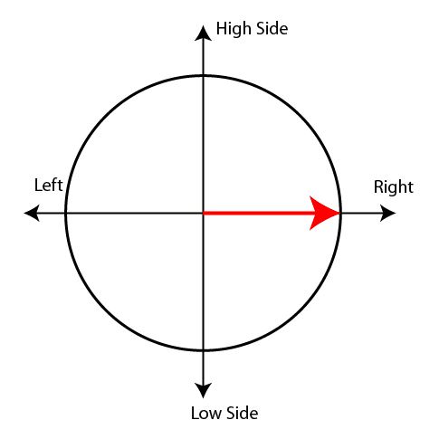
Toolface at 90 degree – it means that a mud motor is lined up to turn the right only but there is no change in inclination.


Figure 5 - Toolface at 90 degree
Figure 5 – Toolface at 90 degree

Toolface at 270 degree – it means that a mud motor is lined up to turn the left only but there is no change in inclination.


Figure 6 - Toolface at 270 degree
Figure 6 – Toolface at 270 degree

Toolface at 45 degree - it means that a mud motor is lined up to turn the right and build angle.

Figure 7 - Toolface at 45 degree

Toolface at 135 degree - it means that a mud motor is lined up to turn the right and drop angle.

Figure 8 - Toolface at 135 degree

Figure 8 - Toolface at 135 degree

Toolface at 225 degree - it means that a mud motor is lined up to turn the left and drop angle.


Figure 9 - Toolface at 225 degree
Figure 9 – Toolface at 225 degree

Toolface at 315 degree - it means that a mud motor is lined up to turn the left and build angle.

Figure 10 - Toolface at 315 degree
Figure 10 – Toolface at 315 degree

Summary – The illustration below shows the meaning of the toolface on each location.

Figure 11 - Toolface Diagram Summary
Figure 11 – Toolface Diagram Summary

Directional Drilling Books

You Need To Watch This – Dropped Casing Incident

$
0
0

Dropped object is one of the most dangerous accidents on the rig therefore we would like to share this footage so you need to watch this. This short VDO can change your life.


You really need to watch this.

What Would We Learn from This Situation?

dropped-casing-fb

  • Always watch out for escape route.
  • Drop object can be happened anytime.
  • Always ensure the surrounding around you.
  • Do not trust the equipment all the time even though it has been tested before using.
  • Always ensure good communication.
  • Always check safety devices.
  • Always perform the inspection.
  • Etc

What have you learn from this VDO?

  • Please feel free to share with us.

Determine Bottom Hole Pressure from Wellhead Pressure in a Dry Gas Well

$
0
0

Gas behaves differently from fluid therefore you cannot use a simple hydrostatic formula to determine reservoir pressure. Gas is compressible but fluid is incompressible.

Bottom-Hole-Pressure-from-Wellhead-Pressure-in-a-Dry-Gas-Well

The formula to determine the bottom hole pressure of dry gas well is shown below;

equation 1


Where; Pbh = bottom hole pressure in psia (absolute pressure)

Pwh = wellhead pressure in psia (absolute pressure)

H = true vertical depth of the well

Sg = specific gravity of gas

R = 53.36 ft-lb/lb-R (gas constant for API standard condition air)

Tav = average temperature in Rankin (Rankin = Fahrenheit + 460)

Example: The dry gas well is shut in and the well head pressure is 2,000 psig (gauge pressure). The average wellbore temperature is 160 F. Gas specific gravity is 0.75. The well is 9,000’ TVD and the wellhead is on land. Determine the bottom hole pressure and compare the result if you use a normal relationship from hydrostatic pressure calculation.

Pwh = 2,000 + 14.7 = 2,014.7 psia

H = 9,000 TVD

Sg = 0.75

Tav = 160 + 460 = 620 °R

equation 2

Pbh = 2,471 psig

Pbh = 2,471 – 14.7 = 2,456 psia

If you use hydrostatic pressure calculation, the bottom hole pressure is calculated by the following equation.

Pbh = Pwh + (0.052 x average gas density (ppg) x TVD of the well, ft)

Average air density at 160 F is 6.404 x 10⁻²  (lb/ft3) = 8.56 x 10⁻³ ppg

Ref: http://www.engineeringtoolbox.com/air-density-specific-weight-d_600.html

Average gas density at 160 F = gas specific gravity x Average air density at 160 F

Average gas density at 160 F = 0.75 x  8.56 x 10-3 ppg = 6.42 x 10⁻³ ppg

Pbh = 2000 + (0.052x6.42 x 10-3x9,000)= 2003 psia

As you can see from the calculation, the hydrostatic pressure cannot be used to determine the bottom hole pressure of the dry gas well. It will give you inaccurate result.

Ref book: Drilling Formula Book Formulas and Calculations for Drilling, Production and Workover, Second Edition

Oilfield Salary Survey and Comparison Study Based on Q3 2014

$
0
0

We’ve collected salary information from the most trusted oilfield website, rigzone.com, about salary and compensation for Q3 2014. At this time, we have the comparison between Q1 salary and Q3 salary.

oilfield-salary-survey-q3-12014

Oilfield Salary Based On Geographical Locations Based on Q3 2014 Data

Africa Average Income = 101,720 USD/year
Australia & Oceania Average Income = 10,4927 USD/year
Central Asia Average Income = 78,143 USD/year
East & SE Asia Average Income = 84,164 USD/year
Europe Average Income = 113,316 USD/year
Middle East Average Income = 76,344 USD/year
North America Average Income = 90,058 USD/year
South America Average Income = 85,105 USD/year
Southern Asia Average Income = 72,157 USD/year

The chart below demonstrates overall income based on Geographical information.

salary survey 19 04 2014_0015_figure 1

Figure 1 - Average Income (USD/Yr) Based on Geographical Area as of Q3 2014

The chart is the comparison between Q1 and Q4 based on the geographical area.

salary survey 19 04 2014_0014_figure2

Figure 2 – Average Income (USD/Yr) Based on Geographical Area Comparison Between Q1 and Q3 2014

The chart below show %changes in salary of people on each area.

salary survey 19 04 2014_0013_figure3

Figure 3 – % Change in Average Income (USD/Yr) Based on Geographical Area Comparison between Q1 and Q3 2014

You can see that almost all areas have a decrease in income. East and South East Asia had the most decline by 16.1%, however; only in Southern Asia area; people by average get increase in salary by 0.19%.

Globally, average income of oilfield personnel decreases by 3.8% when compared Q3 and Q1 2014.

Oilfield Salary Trend from 2011 – 2014 Based on Geographical Area

The following charts demonstrate income trends for all areas and each location.

salary survey 19 04 2014_0012_Figure 4

Figure 4 - World Wide Average Income Trend (USD/Yr)

salary survey 19 04 2014_0011_figure 5

Figure 5 - Africa Average Income Trend (USD/Yr)

salary survey 19 04 2014_0010_figure6

Figure 6 - Australia & Oceania Average Income Trend (USD/Yr)

salary survey 19 04 2014_0009_figure7

Figure 7 – Central Asia Average Income Trend (USD/Yr)

salary survey 19 04 2014_0008_figure8

Figure 8 - Europe Average Income Trend (USD/Yr)

salary survey 19 04 2014_0007_figure9

Figure 9 - East and South East Average Income Trend (USD/Yr)

salary survey 19 04 2014_0006_figure10

Figure 10 - Middle East Average Income Trend (USD/Yr)

salary survey 19 04 2014_0005_figure11

Figure 11 – North America Average Income Trend (USD/Yr)

salary survey 19 04 2014_0004_figure12

Figure 12 – South America Average Income Trend (USD/Yr)

salary survey 19 04 2014_0003_figure13

Figure 13 - Southern Asia Average Income Trend (USD/Yr)

Oilfield Salary Based On Job Discipline Based on Q3 2014 data

Average Income of Personnel in Drilling = 119,690 USD/Yr
Average Income of Personnel in Geoscience = 100,108 USD/Yr
Average Income of Personnel in Maritime = 99,154 USD/Yr
Average Income of Personnel in Management / Support = 90,791 USD/Yr
Average Income of Personnel in Production = 88,833 USD/Yr
Average Income of Personnel in Engineering = 85,609 USD/Yr
Average Income of Personnel in Oilfield Service = 83,934 USD/Yr
Average Income of Personnel in Health Safety Environment = 82,872 USD/Yr
Average Income of Personnel in Trades = 75,222 USD/Yr

salary survey 19 04 2014_0002_figure14

Figure 14 – Average Income (USD/Yr) Based On Job Discipline


The chart below shows the comparison between Q3 and Q1 2014 income based on job functions.

salary survey 19 04 2014_0001_figure15

Figure 15 – Average Income (USD/Yr) Based On Job Discipline Comparison between Q1 and Q3 2014

The chart below shows the changes of income between Q1 and Q3 2014.

salary survey 19 04 2014_0000_figure16

Figure 16 – % Change in Average Income (USD/Yr) Based On Job Discipline Comparison between Q1 and Q3 2014

People working in the production part has the most decline by 4.9% but personnel in maritime has increased income by 2.5%.
Conclusion: The statistics show that most of people in the upstream industry get paid less and we think the main factor is the oil price (WTI) which is about 67 $/bbl as of early December 2014. Low oil price will slow down the industry because several exploration and production projects will not meet economic criteria. We will update this information again in next few quarters to see any changes.
Data source: Rigzone.com

Something wrong while pulling out

$
0
0

This is a few second vdo showing how fast the unexpected can be happened on the rig floor while tripping.

What was happened?

toH-wrong

These are the possible causes.

  • Parted pipe
  • Stuck pipe
  • Bail failure
  • Trapped pressure
  • Operator error
  • Pipe handing equipment failure
  • Etc

 We don’t really know the root cause but what we can learn from this incident.

  • Driller must operate within the limit.
  • Driller must now the weight before pulling out.
  • Personnel must not stay close to the rotary table while pulling out.
  • Driller must inform the floor hand not to close to the floor while tripping out.
  • Everybody must aware of unexpected situation
  • Everybody always asks What-If.

What is your thought about this case?

Please share with us in order to make a safer work place.

Viewing all 497 articles
Browse latest View live


<script src="https://jsc.adskeeper.com/r/s/rssing.com.1596347.js" async> </script>