Quantcast
Channel: Drilling Formulas and Drilling Calculations
Viewing all 497 articles
Browse latest View live

Lost Circulation and Well Control

$
0
0

Lost circulation is a situation when drilling fluid losses downhole because formation(s) is fractured. There are three levels of lost circulation which are seepage loss, partial loss and total loss.

27-Lost-Circulation-and-Well-Control

Seepage loss is a situation when the mud volume loses into formation at very minimal and this will have no or little effect for a drilling operation.

Partial loss is a situation when some volume of drilling fluid loses into the well and you get some drilling mud volume back on surface. Not only do you lose the fluid volume, but you may have ballooning issue to deal. However, this type of fluid loss will not lead to well control situation because the total hydrostatic pressure does not decrease.

Total loss is the worst situation because there is no mud returning back to surface and the mud level will drop to any level down hole. Losing a lot of fluid into the well will directly affect hydrostatic pressure at the bottom. If you cannot keep the hole full, it might be a time when the hydrostatic pressure is less than the reservoir pressure. Eventually, a well control situation will be happened.

How Mud Fluid Volume Drop Before The Well Kicks In?

This example will demonstrate you how to determine volume loss before the well kick in.

9-5/8” casing was set at 6,000MD/6,000’TVD (vertical well).

9-5/8” casing : N-80, 40 lb/ft, 8,835” ID

Leak off test at 9-5/8” casing shoe = 15.0 ppg equivalent mud weight

Current hole depth is 10,000’MD/10,000’TVD and current mud weight is 12.5 ppg

Expected formation pressure at 10,000’TVD is 12.0 ppg

Annular capacity = 0.0515 bbl/ft

Drillstring capacity = 0.0178 bbl/ft

Figure 1 - Well Schematic

Figure 1 - Well Schematic


The well has a total loss. Height of fluid which is equal to formation pressure can be described here.

Formation pressure = Hydrostatic pressure

12.0 x 0.052 x 10,000 = 12.5 x 0.052 x H

H = 9,600 ft

You need 9,600 ft TVD of 12.5 ppg mud in order to balance formation pressure. If you have less than this depth, the well is in underbalanced condition.

Figure 2 -Maximum Fluid Loss


It means that the fluid can drop 400 ft before the kick comes into the well. Then we calculate how much volume based on 400 ft height. For this case, measured depth is equal to true vertical depth because of a vertical well.

Total mud volume = mud in annulus + mud in drill string

Total mud volume = (Annular capacity x 400) + (Drillstring capacity x 400)

Total mud volume = (400 x 0.0515) + (400 x 0.0178) = 27.72 bbl.

For this scenario, the maximum volume lost down hole before the well control situation is occurred is 27.72 bbl.  You can see that it will not take much mud loss before you will have the problem. In the real situation, you need to keep the well full all the time. If the mud is run out, you need to pump water to fill the hole. Allowing more fluid to drop will create you bigger problem because you will need to deal with several issues as well control, lost circulation, stuck pipe, etc.

Conclusion: Always Keep The Hole Full

Reference books: Well Control Books


Oilfield Casing Data Sheet Free Download

$
0
0

Casing information is very important part of working in the oilfield. This information is used in several calculations as expected displacement volume, cement calculation, stuck pipe calculation, burst/collapse, casing design, etc. Therefore our team collects casing data into one spreadsheet and pdf file for you to download.

casing-Data-sheet-cover

What is Information inside the Casing Data Spreadsheet?

  • Casing data for 834 types of casing
  • Range of casing : 4-1/2” casing to 20” casing
  • Casing specification: OD, ID, Nominal weight, Grade, Burst & Collapse Pressure, Internal Yield Pressure Minimum Yield (psi), Joint Strength, Body Yield Strength, Wall Thickness, Drift Diameter, Displacement (bbl/ft) and Capacity (bbl/ft)
  • There are 2 versions which are Excel file and pdf file. Both of them have the same data so you can pick any file that your computer can open. Additionally, these files are properly setup for print.
  • The data in the spreadsheet is well organized so you can find what you need so easily (Figure 1).

 figure 1 casing spec sheet

Figure 1 - Inside The Spreadsheet

Download the casing data sheet from the following links:

Excel versionCasing data specification sheet in MS Excel Version 

PDFversion – Casing data specification sheet in PDF version 

If you like this information, please feel free to share with your friends/ co-workers. Finally, please feel free to give us feedback about this one.

Choke Line Friction – How Is It Affect Deepwater Well Control?

$
0
0

Choke line friction (CLF) is the frictional pressure which is generated while circulating mud through choke or kill line. For surface stack, the choke line friction is negligible because the choke line is short therefore the friction pressure is so small. However, the choke line friction in deepwater operation has a big effect bottom hole pressure. Killing the well without considering the CLF will add excessive pressure and it increases the chance of fracturing formation at casing shoe or anywhere in the well.

choke-Line-Friction

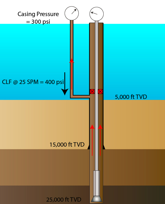
Figure 1 is a simple diagram showing the direction of CLF while a normal circulation is performed. The choke line friction will be in the opposite direction of flow which is downwards to the wellbore. This additional friction will increase the bottom hole pressure.

Figure 1 - Direction of Choke Line Friction Pressure

Figure 1 – Direction of Choke Line Friction Pressure


Example: Water depth = 5,000 ft

Shoe depth = 15,000 ft TVD

Hole depth = 25,000 ft TVD

Casing pressure = 300 psi

Current mud weight = 12.0 ppg

Choke line friction pressure @ 25 spm = 400 psi

Neglect annular pressure loss in the well due to low flow rate

Figure 2 - Example of CLF

Figure 2 - Example of CLF

What is the shoe pressure if we bring pump up to speed without considering CLF?

Figure 2 is the diagram based on the question and you need to add the CLF and casing pressure. Bottom hole pressure at the shoe is calculated by the following equation;

BHP @ shoe = MW + (Casing Pressure + Choke Line Friction) ÷ 0.052 ÷ Shoe TVD

BHP @ shoe = 12.0 + (300 + 400) ÷ 0.052 ÷ 15,000 = 12.9 ppg

Without compensating the CLF, the bottom hole pressure will increase by 0.9 pgg which can possibly break down the shoe.

In order to maintain constant bottom hole pressure, the casing pressure must be compensated by CLF. In the next topic, we will discuss how to measure CLF and maintain the bottom hole pressure while bring the pump up to speed.

Reference books: Well Control Books

Beautiful Oilfield Calendar 2015 Free Download

$
0
0

In next few days, we will pass 2014 and start a new journey in 2015. For this year, we would like to make a special oilfield calendar 2015 for everybody. There are a total of 12 months with different themes and you click on each image to download the big files. You can set each photo on your computer screen.

2015-calendar

January

1-Jan

February

2-feb

March

3-mar

April

4-apr

May

5-may

June

6-jun

July

7-jul

August

8-aug

September

9-sep

October

10-oct

November

11-nov

December

12-dec

We wish you would enjoy our special oilfield calendar 2015. Please feel free to share with your friends, colleges, family members, etc.

Note: All images are legally purchased from Shutterstock.com and Thinkstockphotos.com

What is the longest, deepest and largest hole ever drilled on earth?

$
0
0

This is very interesting information about the longest, deepest and largest hole ever drilled on earth. You will be amazed how people can overcome the limit of nature.

facebook-cover

Longest Hole

In May 2008, GSF Rig 127 operated by Transocean drilled (BD-04A) in the Al Shaheen Oil Field for Maersk. It has a measured length of 40,320 feet (12.3 km) with a horizontal section of 35,770 feet (10.9 km). Maersk Oil’s well also extended the company’s previously held world record for the longest horizontal well by 9,000 feet (2.7 km). The entire horizontal section of the well is placed within a reservoir target which is only 20 feet (6 m) thick. And it was completed in 36 days. Incident free.

Sakhalin-1_P

Then on 28 January 2011, Exxon Neftegas Ltd., operator of the Sakhalin-1 project, drilled the then world’s longest extended-reach well. It has surpassed both the Al Shaheen well and the previous decades-long leader Kola Superdeep Borehole as the world’s longest borehole. The Odoptu OP-11 Well reached a measured total depth of 40,502 ft (12,345 m) and a horizontal displacement of 37,648 ft (11,475 m). Exxon Neftegas completed the well in 60 days.

sakhalin1

On 27 August 2012, Exxon Neftegas Ltd beat its own record by completing Z-44 Chayvo well. This ERD well reached a measured total depth of 40,604 ft (12,376 m).


Deepest Hole


Today, the deepest hole ever created by mankind lies beneath the tower on Russia’s Kola Peninsula, near the Norwegian border at about the same latitude as Prudhoe Bay, Alaska. And It is not oil or gas that is being sought with the Kola well, but an understanding of the nature of the earth’s crust.

In 1962, a drilling effort was led by the USSR’s Interdepartmental Scientific Council for the Study of the Earth’s Interior and Superdeep Drilling, which spent years preparing for the historic project. It was started in parallel to the Space Race, a period of intense competition between the U.S. and U.S.S.R. The survey to find a suitable drill site was completed in 1965 when project leaders decided to drill on the Kola Peninsula in the north-west portion of the Soviet Union. After five more years of construction and preparations, the drill began on 24 May 1970 using the Uralmash-4E, and later the Uralmash-15000 series drilling rig.

A number of boreholes were drilled by kicking off the central hole. The deepest, SG-3, reached 40,230 ft (12,262 m) in 1989, and is the deepest hole ever drilled, and the deepest artificial point on Earth (the previous record holder was the Bertha Rogers well in Oklahoma—a gas well stopped at 32,000 feet when it struck molten sulfur) .In terms of true depth, it is the deepest borehole in the world. For two decades it was also the world’s longest borehole, in terms of measured depth along the well bore, until surpassed in 2008 by the 12,289-metre-long (40,318 ft) Al Shaheen oil well in Qatar, and in 2011 by 12,345-metre-long (40,502 ft) Sakhalin-I Odoptu OP-11 Well (offshore the Russian island Sakhalin).

It’s possible to draw a reasonable cross section of the earth based purely on remote geophysical (largely seismic) methods, but unless on-the-spot checks can be made, there will always be a certain amount of guesswork involved. Digging down to take a look compares with studies made from the surface in the way that exploratory surgery compares with taking an X-ray.

An unexpected find was a menagerie of microscopic fossils as deep as 6.7 kilometers below the surface. Twenty-four distinct species of plankton microfossils were found, and they were discovered to have carbon and nitrogen coverings rather than the typical limestone or silica. Despite the harsh environment of heat and pressure, the microscopic remains were remarkably intact.

The Russian researchers were also surprised at how quickly the temperatures rose as the borehole deepened, which is the factor that ultimately halted the project’s progress. Despite the scientists’ efforts to combat the heat by refrigerating the drilling mud before pumping it down, at twelve kilometers the drill began to approach its maximum heat tolerance. At that depth researchers had estimated that they would encounter rocks at 212°F (100°C ), but the actual temperature was about 356°F (180°C)– much higher than anticipated. At that level of heat and pressure, the rocks began to act more like a plastic than a solid, and the hole had a tendency to flow closed whenever the drill bit was pulled out for replacement. Forward progress became impossible without some technological breakthroughs and major renovations of the equipment on hand, so drilling stopped on the SG-3 branch. If the hole had reached the initial goal of 15,000 meters, temperatures would have reached a projected 572°F (300°C).

The last of the core samples to be plucked from from the borehole were dated to be about 2.7 billion years old at the bottom (for comparison, the Vishnu schist at the bottom of the Grand Canyon dates to about 2 billion years—the earth itself is about 4.6 billion years old).

When drilling stopped in 1994, the hole was over seven miles deep, making it by far the deepest hole ever drilled by humankind. But even at that depth, the Kola project only penetrated into a fraction of the Earth’s continental crust, which ranges from twelve to fifty miles thick.


Largest Hole

largest

There is a diamond mine located on the outskirts of Mirny, a small town in eastern Siberia. That begun in 1955, and is now 1,722 feet (.52 km) deep and 0.78 miles (1.2 km) in diameter. This hole is impressive. To get to the base of the pit, massive 20-foot tall rock-hauling trucks travel along a road that spirals down from the lip of the hole to its basin. The round-trip travel time is two hours. The Mirny diamond mine has a volume of over 7 BILLION bbls (1.1 billion m3) and its only the second-largest man-made hole in the world.


The Bingham Copper Mine in Utah IS the largest man-made hole in the world. The mine has been in production since 1906, and has resulted in the creation of a pit over 0.6 miles (0.97 km) deep, 2.5 miles (4 km) wide, and covering 1,900 acres (770 ha). It has an approxamit volume of 77.5 billion bbls (12.3 billion m3).

Ref:

https://knowledgebox.drillutions.com/question/10/what-is-the-deepest-longest-and-widest-hole-ever-drilled/

http://en.wikipedia.org/wiki/Sakhalin-I

http://en.wikipedia.org/wiki/Kola_Superdeep_Borehole

Why Was This Well Control Situation Happened?

$
0
0

You need to watch the VDO below. It demonstrated the situation before the blowout was occurred.

These are some possible root causes which contributes to this situation.

why-this-well-control-happen

  • Improper hole fill
  • Lack of properly tracking the trip sheet
  • Incompetent crew
  • Full Openning Safety Valve and IBOP were not properly prepared to stab in. The crew were looking at them when they found out that the flow was coming up from the drillstring.
  • No float valve in the drillstring
  • Take to long to shut the well in. You can see only 4 minutes before the massive blowout was blowing on the rig floor.
  • Lack of well control knowledge and training
  • Possible to swab the well in
  • What do you think about this well control situation?

Is this preventable?

Please feel free to leave us some comments below.  Additionally, you can learn a lot of well control knowledge from our website – Well Control

How To Measure Choke Line Friction (CLF) for Deepwater Well Control

$
0
0

Choke Line Friction is one of critical figures that personnel on the rig need to know and this numbers can be determined.

how-to-measure-CLF

The procedures for the choke line friction determination are as follows;


1. Line up to circulate into choke line

Figure 1 - Line Up

Figure 1 - Line Up

2. Circulate down the choke line and up into riser. This will not add significant pressure to bottom hole. When you measure the pressure you need to know mud density and rheology and it is very important that you wait until you get the stabilized pressure reading.

Figure 2 - Circulate down choke line
Figure 2 – Circulate down choke line

3. Record CLF at expected kill rates for well control as 10 SPM, 20 SPM, 30 SPM, etc. This will give you an idea how much CLF at particular flow rate. The table below demonstrates the pre-recorded CLF
Flow Rate (SPM) Choke Line Pressure (psi) Mud Weight (ppg)

Table 1 Pre Recorded CLF

This procedure can be performed any time while drilling and we recommend you to check the CLF when drilling fluid properties have been changed a lot from the previous test. Additionally, you can use the same procedure to measure the frictional pressure at the kill line too.

Reference books: Well Control Books

How To Compensate Choke Line Friction For Deep Water Well Control

$
0
0

Choke line friction pressure will increase bottom hole pressure while circulating to kill the well therefore it must be compensated in order to maintain the bottom hole pressure relatively constant. This section will describe how to compensate the choke line friction while bring pump up to speed.

How-To-Compensate-Choke-Line-Friction-For-Deep-Water-Well-Control

Compensate The Choke Line Friction By Using Casing Pressure Gauge

 At static conditionthe bottom hole pressure can be described like this

Bottom Hole Pressure = Hydrostatic Pressure in Annulus + Casing Pressure

Figure-1---Bottom-hole-pressure-at-static-condition

Figure 1 – Bottom hole pressure at static condition

At dynamic conditionthe bottom hole pressure can be described like this

Bottom Hole Pressure = Hydrostatic Pressure in Annulus + Casing Pressure + Choke Line Friction + Annular Pressure Loss

We will use acronym like this to make it easy.

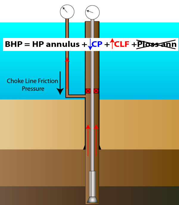
BHP = HP annulus + CP + CLF + P loss annulus

Since the pumping rate while performing well control operation is not high therefore the pressure loss in the annulus is negligible.

BHP = HP annulus + CP + CLF + P loss annulus

While circulating, CLF will increase therefore CP must be intentionally decreased at the same amount of CLF in order to keep the bottom hole pressure relatively constant.

BHP = HP annulus + ↓CP + ↑CLF

Figure-2---Bottom-Hole-Pressure-at-Dynamic-Condition

Figure 2 – Bottom Hole Pressure at Dynamic Condition

Let’s look into this example for more understanding. The well is shut in with 500 psi shut in casing pressure and 300 psi shut in drill pipe pressure. The plan is to circulate using 30 SPM.

The table below is the pre-determined CLF.

table-CLF

If we select 30 SPM as a kill rate, you will get 450 psi CLF therefore you need to reduce casing pressure by 450 psi to maintain the bottom hole pressure (see Figure 3).  The casing pressure after the kill rate is fully established will be equal to initial shut in casing pressure minus CLF which is 50 psi.

Figure-3---Compensate-CLF-by-Reducing-CSG-pressure

Figure 3 - Compensate CLF by Reducing CSG pressure


Figure 4 shows simple charts representing the compensated casing pressure while bringing the pump up to kill rate at 30 SPM.

Figure-4---Chart-Showing-SPM-and-CP

Figure 4 - Chart Showing SPM and Casing Pressure (CP)

Compensate The Choke Line Friction By Kill Line Pressure

This is another way to start circulation with constant bottom hole pressure by using kill line pressure gauge.  Firstly, the circulation path is lined up to the choke line up to surface and the valves in the kill line must be opened just for reading the kill line pressure. Kill line will not be used as a circulation path. At this point, choke and kill like can read pressure separately.

Secondly, the circulation is brought up to kill rate by holding kill line pressure constant. The benefit of using the kill line pressure is that there is no friction pressure at the kill line side because no fluid is circulated through the kill line.  With the maintained kill line pressure, choke pressure will decrease by the amount of CLF at a particular flow rate. The static kill line pressure will maintain the bottom constant bottom hole pressure, like casing pressure gauge on a surface BOP well control. Figure 5 demonstrates the line up and the circulation path.

Figure-5---Compensate-CLF-by-Using-Kill-Line-Pressure-Gauge

Figure 5 – Compensate CLF by Using Kill Line Pressure Gauge

For some advanced subsea BOP’s, they are equipped with BOP gauges. The BOP pressure gauge can be used to maintain the bottom hole pressure constant, like the kill line pressure gauge. The process is the same as the procedure when you use kill line pressure gauge but only you monitor the BOP pressure gauge. Figure 6 shows the configuration of CLF compensation using the BOP gauge.

Figure-6---Compensate-CLF-by-Subsea-BOP-Pressure-Gauge

Figure 6 – Compensate CLF by Subsea BOP Pressure Gauge

Reference books: Well Control Books


Platform Installation Video

$
0
0

This is amazing footage about platform installation. The 14-minute footage will show you the process of offshore platform installation and this will show give very clear picture of how people install the offshore process facility. Please check out the VDO below :)

What will you see in this footage?

platform-stallation
• Platform jacket transportation
• Securing the jacket with the platform piles
• Installation of the platform
• Completion of the platform
• etc
We wish you would enjoy watching this amazing VDO.

If you have any comments, please feel free to share with us.

Choke Line Friction Pressure as Kill Weight Mud Approaches the Surface

$
0
0

Choke Line Friction pressure (CLF) has directly affect on the bottom hole pressure while performing well kill operation in a deepwater operation. You may be able to circulate the kick out of the well without breaking the shoe down with the current mud weight however; the well can be fractured when the kill weight mud reaches the surface due to excessive CLF.

31-CLF-as-KWM-approches-the-surface

How Kill Weight Mud and CLF Will Break the Shoe

When the kill mud is circulated from the bit to surface as per the second circulation of driller’s method, drill pipe pressure is held constant and the choke is gradually opened. Once the choke is in the fully open position, the back pressure due to choking back the well is gone but the CLF is still there. With the heavier weight, the CLF with KWM will be more than the CLF with the original mud. If the hydrostatic pressure is more than the fracture pressure, the formation will be broken down.  Let’s take a look at the following calculation to get clearer picture of this topic.

Example: The well information is listed below;

  • Water depth = 5,000 ft
  • Shoe depth = 15,000 ft TVD
  • Hole depth = 25,000 ft TVD
  • Kill mud weight = 12.5 ppg
  • Choke line friction pressure @ 25 spm = 500 psi with 12.5 ppg
  • Shoe fracture pressure = 13.0 ppg
  • Neglect annular pressure loss in the well due to low flow rate

Casing pressure is 0 psi due to fully opened choke,  the shoe pressure be determined by the following calculation process.

Figure-1---Shoe-Pressure-with-Original-Mud-Weight


Figure 1 - Shoe Pressure with Original Mud Weight

BHP @ shoe = MW + ((Casing Pressure + Choke Line Friction) ÷ 0.052 ÷ Shoe TVD)

BHP @ shoe = 12.5 + ((0+500) ÷ 0.052 ÷ 15,000) = 13.2 ppg (round up figure)

Figure-2---Shoe-is-fractured-due-to-CLF

Figure 2 – Shoe is fractured due to Choke Line Friction

Without any surface casing pressure (Figure 2), the bottom hole pressure (13.2 ppg) is still exceed the shoe fracture gradient (13.0 ppg). Therefore, the formation will be broken.  As you can see from the example, the excessive CLF while kill weight mud is coming out to surface can fracture the formation.

How To Prevent the Effect of Choke Line Friction Pressure

There are few ways to prevent this issue as listed below;

  • Use the large choke diameter as much as possible – This should be done at the rig selection stage. It will cost additional cost if you want the existing choke line to be upgraded.
  • Reduce kill rate – Reduce flow rate will cut down choke line friction due to square relationship. However, the circulating time will increase.
  • Circulate both choke line and kill line at the same time – The flow will distribute to both choke and kill line; therefore, this option will still maintain the same flow rate but the frictional pressure is reduced by approximately 75% due to square relationship. There are few disadvantages too. The first one is that without BOP sensor, you need to back off the friction pressure manually and you need to know the frictional pressure by circulating through choke and kill line together. You also have the potential to loss of redundancy if both lines are plugged off.

Reference books: Well Control Books


Understand about Formation Pressure in Drilling

$
0
0

Formation pressure is important information for well planning and operation because it impacts on several things as well control, casing design, drilling fluid program, pore pressure prediction, etc.  We will discuss about formation pressure in a basic term for drilling personnel.

During an era of sedimentation and erosion, little grains of sediment are constantly building above each other, usually in an environment of full irrigation. As the sediment thickness of the base layer increases, the sediment grains are packed strongly near to each other, and some water is excluded from the small pore spaces. Though, if the pore spaces through the deposit sediments are connected to the top pressure surface, the fluid at any depth in the sediment will be same as that which would be found in a simple column of fluid.

understand-formation-pressure

The pressure of fluid in sediment pores would only be reliant on the fluid density in pore space and depth of the pressure measurement (equal to the elevation of the column of liquid). It will also be independent of size of the pore or throat geometry. The pressure of the fluid in the pore space (the pore pressure) can be measured and plotted against depth as shown in Figure 1.

Figure-1---Pressure-Vs-Depth-Plot

Figure 1 – Pressure Vs Depth Plot

The pressure in the formations to be drilled is often expressed in terms of a pressure gradient as psi/ft. This gradient is consequential from a line passing all through an exacting arrangement of pore pressure and a datum point at surface and is namely the pore pressure gradient (Figure 2).

Figure-2---Pressure-Gradient

Figure 2 - Pressure Gradient

When pore throats interconnected through sediment, the fluid pressure at any depth in sediment will be identical of that would be established in a simple column of fluid and consequently the pore pressure gradient is a straight line as illustrated in Figure 1. The tangent of the line is pressure gradient shown in Figure 2.

Representing pore pressure in pressure gradient unit is quite convenient for calculation and easy to present to everybody. If drilling mud density is presented in the same pressure gradient unit, at each depth of interest, you can compare pressure in order to ensure that the well is still in over balance condition. The Figure 3 is a chart showing the pore pressure gradient and mud gradient. The degree of difference between the pore pressure and the mud pressure at any particular depth is overbalance pressure at.

Figure-3---Overbalance-Based-on-Pressure-Plot

Figure 3 – Overbalance Based on Pressure Plot

Within the pore space of sedimentary formations contain most of the fluids with proportions of salt and known as brines. The dissolved salt matter can vary from 0 – (over) 200,000 ppm. Likewise, pore pressure gradient vary from 0.433 psi/ft (fresh water) to around 0.50 psi/ft. Pore pressure in most geographical areas, the gradient is roughly 0.465 psi/ft with assumption of 80,000 ppm salt concentration. This figure is defined as the normal pressure gradient.

Any pressure formation deviates from the normal pressure gradient is named ‘Abnormal pressures’. The abnormal pressure affects both engineering and operation of drilling. There are several reasons why the abnormal pressure zones are occurred and we will discuss it later on.

Reference books: Well Control Books

Review and Download Introduction to Wellbore Position Ebook

$
0
0

Have you ever wonder how the directional tool works, why we need GYRO tool, what magnetic interference is ,etc. It is very difficult to find the answer even though we have internet.  Recently, my friend shares me this excellent book, Introduction to Wellbore Positioning by Prof Angus Jamieson at University of the Highlands & Islands.  This is one of the best books regarding wellbore positioning. In the book, only does it have the text, but also contains tons of picture which will help learners to get more understanding of this topic.

What Will You Learn from the Introduction to Wellbore Positioning?

cover

  • Coordinate Systems and Geodesy
  • Changing from One Map System to Another
  • True North, Grid North and Convergence
  • The Earth’s Magnetic Field
  • Principles of MWD and Magnetic Spacing
  • In-Field Referencing
  • Survey Calculation Methods
  • Survey Frequency
  • Gyro Surveying
  • Basic Gyro Theory
  • When to Run Gyros
  • Correcting for Sag
  • Correcting for Magnetic Interference
  • Multi Station Analysis
  • Correcting for Pipe and Wireline Stretch
  • Human Error v Measurement Uncertainty
  • Understanding Error Models
  • The ISCWSA Error Models: Introduction
  • The ISCWSA Error Models: Explanation and Synthesis
  • Anti-collision Techniques
  • Planning for Minimum Risk
  • Basic Data QC
  • Advanced Data QC
  • Tortuosity
  • Some Guidelines for Best Practice
  • Relief Well Drilling
  • Subsea Positioning

Some of images in this book

image-1

image-2

image-3

Please download from this link –

facbook-cover-introduction-to-wellbore-positioning

http://www.uhi.ac.uk/en/research-enterprise/Introduction%20to%20Wellbore%20Positioning_V01.5.14.pdf

If you think, this would be advantage for your friends, please feel free to share with them.

Pore Pressure Evaluation While Drilling Is Important For Well Control

$
0
0

During a drill well on paper phase, wells might be planned based on available data from offset wells or nearby areas. This information may deviate from the actual drilling phase due to several reasons therefore it is very critical to have good monitoring and evaluating pore pressure while drilling. The actual pore pressure will dictate where to set the casing, how much the actual mud weight should be, what potential problems are, etc.

The actual reservoir pressure obtained while drilling will be used to determine right mud density in order to ensure an adequate primary well control. Besides the well control, the proper mud weight can help us in several aspects such as minimizing lost circulation and pipe sticking and maximizing a rate of penetration. You can achieve the trouble free drilling operation.

pore Pressure evaluation while drilling

The following indicators can demonstrate abnormally pressured reservoirs;

  • Higher porosity
  • Higher permeability
  • Higher sonic velocity
  • Lower shale density and resistivity
  • Lower water salinity in formation

The concept of evaluating pore pressure while drilling is to measure the changes in these properties which vary with different lithology and area of drilling. You need to take into account about the lithological variation when interpreting data. Moreover, measuring of these parameters can be used to quantitatively estimate. It will give you the relative information when compared to the overall trend.

Let’s take a look at shale density as an example. The shale density is typically denser over depth; however, a high pressure zone tends to have higher porosity and lower bulk density because the reservoir pressure inside will push the rock grains. While drilling, the shale density should be plotted against the depth because you can see the normal trend. When you see decrease in the shale density trend, it shows you that the abnormally pressured zone is there (see Figure 1).

Figure 1 - Shale Density Plot

Figure 1 – Shale Density Plot

Nowadays, Logging While Drilling (LWD) tools are widely used because they can measure reservoir data and send to the surface real time. This will help us closely and accurately monitor the well to see any changes in the parameters. These tools can assist you to make adjustment in mud weight while drilling effectively. If you want precise reservoir pressure, some service companies can provide formation tester service while drilling. It might take time but you will know exactly where you are and how accurate of the pore pressure curve.

Surface real time logging is another way to evaluate the pore pressure and there are some mud logging companies also provides pore pressure analysis. These following changes can be a possible high pressure zone;

  • Abnormal change in ROP
  • Increase in return line temperature
  • Increase in drilling drag and torque
  • Increase in cutting size and shape
  • Increase in trip, connection and/or background gas
  • Decrease in d-Exponent

Conclusion: Monitoring and evaluating the formation pore pressure is the key to achieve drilling free operation especially in unknown areas where you have the limited information. With real time data monitoring both downhole and surface, you can detect changes very quickly and the right decision regarding the mud weight can be made on time. Always listen to the well and you will be fine.

Reference books: Well Control Books

Gas drilling site in Washington County Caught on Fire

$
0
0

This is a very bad oilfield incident happened recently, Drilling Site in Washington County Caught on Fire. According to the NEWS, the failure of the rig equipment results in the fire situation.  The hydraulic oil from ruptured high pressure hose spilled out and caught on fire. We would like to share this news to you in order to raise aware of of oilfield safety.

Equipment failure causes fire at Washington Co. gas drilling site.

Spokesperson said an equipment failure was the cause of a fire at a gas drilling site in Washington County Wednesday evening.

Dispatchers from 911 confirmed calls came in around 5:15 p.m. for a working fire at the Jeffries drilling location near Ross Road in North Strabane Township.

Matt Pitzarella, Range Resources corporate communications and public affairs director, said EST Range and area first responders extinguished the fire shortly after 6:15 p.m.Pitzarella said the company was able to confirm that there were no injuries and that this was not a well control incident.

The fire was a result of an equipment failure on a piece of machinery, which discharged some engine oil that caught fire along with plastic liners used for environmental prevention on the ground of the location, according to Pitzarella.


Pitzarella said Range Resources will work with regulators and first responders to investigate what occurred and “take action to best prevent future incidents from happening.”

In addition, Pitzarella said the company is meeting with area residents who live near the drilling site.

“We very much understand, respect and appreciate the concerns that issues such as this may cause for nearby homes, and Range is currently meeting with area residents to explain what happened and to assist them with any issues this unfortunate matter may have caused,” Pitzarella said in a written statement.

http://www.wpxi.com/news/news/local/active-fire-drilling-site-outside-pittsburgh/nj4sZ/

 Oil from hydraulic line caused fire at gas drilling site

NORTH STRABANE TOWNSHIP, Pa. —Oil from a ruptured hydraulic line is being blamed for sparking a fire at a Washington County gas drilling site Wednesday evening.

But officials with Range Resources and the state Department of Environmental Protection are trying to determine how the oil leaked and was ignited, and how to prevent similar accidents in the future.

The blaze was reported at about 5:15 p.m. at the Range Resources site on Ross Road in North Strabane Township.

Spokesman Matt Pitzarella said Range Resources crews working with local first responders managed to extinguish the flames. No injuries were reported.

Pitzarella says workers failed to put out the fire with a hand-held extinguisher before it spread to a plastic liner used to contain pollutants. County officials say the fire burned the drilling rig and two nearby trailers before it was extinguished about an hour later.

The company said a piece of machinery apparently discharged some engine oil that caught fire along with plastic liners used for environmental prevention on the ground.

DEP spokesman John Poister says some details of the fire “need to be further explained.”

http://www.wtae.com/news/fire-burning-at-north-strabane-gas-well-site/31098032


Fire reported at gas drilling site in Washington County

No one was injured in a fire Wednesday afternoon at a gas drilling site in Washington County.

The fire erupted about 5:15 p.m. at what is known as Range Resources Corp.’s Jeffries drilling location off Ross Road in North Strabane.

Range Resources personnel and firefighters extinguished the flames about an hour later using a specialty foam designed for oil and grease fires, said company spokesman Matt Pitzarella.

He stressed that this was not a gas well fire, per se, and that no residents were evacuated.

“The fire was a result of an equipment failure on a piece of machinery, which discharged some engine oil that caught fire along with plastic liners used for environmental prevention on the ground of the location,“ Pitzarella said.

“As with any incident of this nature, we will work with regulators and first responders to investigate what occurred and take action to best prevent future incidents from happening. … Range is currently meeting with area residents to explain what happened and to assist them with any issues this unfortunate matter may have caused.”

http://triblive.com/news/adminpage/7710115-74/fire-drilling-reported#axzz3R6icTJU9

Basic Understanding about Well Control with Pipe off Bottom

$
0
0

Well control with pipe off the bottom is one of the most serious well control situations because kick below a drillstring can create very complicated situations when compared to a normal well control. This article will teach you about the basic well control when the pipe off bottom.

basic Understanding about Well Control with Pipe off Bottom

There are several well control techniques to manage when the kick comes into the well and it is below the pipe;

  • Use the Volumetric technique. The volumetric well control to let the gas migrate to surface with the bottom hole pressure nearly constant. This option is applicable when the influx is gas.
  • Strip the drillstring back to the bottom. This is applicable with non-migration kicks as water and oil.
  • Strip the drillstring utilizing the volumetric well control. This method can be used when you have a gas influx.
  • Snub (push) the pipe against the wellbore pressure down to the bottom
  • Kill the well off bottom using conventional well control methods as driller’s method and wait and weight. Typically, this is not recommended to use because you won’t get the kick out of the well and you may not be able to determine the kill weight mud correctly.

Since the pipe is off bottom and it is very critical to go back to the bottom to kill the well with the normal well control methods; therefore, there are two special techniques to trip the drillstring back to the bottom which are stripping and snubbing.

Figure 1 - Kick Off Bottom

Figure 1 - Kick Off Bottom

Snubbing – it is when you push the string through the BOP because the weight of the drillstring is less than the upward force created by wellbore pressure. Typically, the snubbing operation cannot be performed with a normal rig set up. It is required several specialized tools which you don’t normally have on the rig. This operation is normally performed by hydraulic workover units.

Stripping – it is when you trip the string through the BOP, typically annular preventer, when the string weight is more than the upward force pushing up from the well.

The kick is below the bit and this can result in same reading on both drill pipe pressure and casing pressure. You don’t know the correct pressure to determine kill weight fluid because both sides don’t have one single fluid column.

Figure 2 - Same Reading on Both Casing and Drillpipe Pressure

Figure 2 - Same Reading on Both Casing and Drillpipe Pressure

The kick type must be identified in order to determine if the volumetric well control will be applied during the stripping operation. By observing surface pressures, if there is increase in surface pressure, it will most likely be gas influx. On other hands, if there is no change, it is a high possibility to be fluid kick. If you take a gas influx, the volumetric control must be considered for stripping operation.

Stripping drillpipe into the well is required to have an inside blow out preventor in the drillstring. The IBOP will prevent the flow to come up and the forward circulation can be performed. It is very critical that the IBOP is in a good condition prior to using it.

For stripping operation, there are two techniques which are annular stripping and ram combination stripping. The annular stripping is quite simple way to strip into the well but the ram combination is quite complicated and you may have more chance to damage the BOP components. If you have a choice for this kind of operation, we would like to recommend you to use the annular stripping technique.

Before the annular stripping operation, it is recommend reducing the annular operating pressure to allow the drill string to be stripped easily and the annular element does not face excessive pressure when the tool joints are pushed through it. Additionally, it might be helpful to have a surge dampener in the closing line in order to maintain constant closing pressure while the tool joints are being stripped through.

Surface pressure is another factor that can limit the annular stripping. Operating life of the annular element will drastically reduce because of high surface pressure. If the well is shut in with high surface pressure, you are required to reduce surface pressure prior to stripping. There are some options to get the surface pressure down as listed below;

  • Bullhead with heavier mud
  • Lubricate and bleed if the influx is on surface
  • Circulate an influx out if you know that the influx is above the bit

For the next topic, we will discuss into some details of this well control method, the related calculations and procedure.

Reference books: Well Control Books


Pressure Drop through Surface Equipment

$
0
0

Pressure drop through surface equipment is one of the components in drilling hydraulics that must be considered. When we talk about surface equipment, we usually refer to those following equipment as a stand pipe, surface hoses, a swivel, a gooseneck and a Kelly.

119 Pressure drop throug surface equipment 1

Surface equipment on the rig – more detail here http://en.wikipedia.org/wiki/List_of_components_of_oil_drilling_rigs

Because of a number of several combinations of surface equipment, four popular combinations are selected and the surface equipment coefficients for calculating pressure loss are shown in the below table.

119 Pressure drop throug surface equipment 2


How to determine the pressure drop thought the surface equipment

  1. Fine out the surface coefficient show in the table above.
  2. Use the following equation to figure out the pressure loss.

119 Pressure drop throug surface equipment 3


Where:

P = pressure loss, psi

W = mud density, ppg

Vf = viscosity correction factor

PV = plastic viscosity, centipoises

Q = flow rate, gpm

Di = inside diameter of pipe, inch

Cse = general coefficient for surface equipment

For more understanding, please following the example to calculate pressure loss through surface equipment

Surface coefficient is in case#2 therefore Cse is 8.

Mud weight = 9.5 ppg

Plastic Viscosity = 12 cp

Flow rate = 600 GPM

119 Pressure drop throug surface equipment 4

P = 155 psi.

Conclusion: With the given example, the pressure drop through surface equipment is 155 psi.

Reference:  Drilling Hydraulic Books

Shallow Gas Hazard in Well Control – Sedco 700 Shallow Gas Incident

$
0
0

Shallow gas is one of the most dangerous incidents in well control because you don’t have the BOP set to be able to control the well. Additionally, shallow gas always happens at the shallow depth as surface hole section where you will have a difficulty to control the well. This footage below show you how serious of the shallow gas in an offshore environment.

Sedco 700 Shallow Gas Blow Out 6 June 2009

Additional details about shallow hazards that you need to know.

shallow Gas Hazard in Well Control Sedco 700

The shallow hazard is a formation that has the possibility to flow to surface without BOP set to control the well. It can be both water and gas kick and it can be happened at any locations as land drilling, shallow offshore environment and floating operations.

Water Flow as Shallow Hazard

The water shallow hazard is caused by natural or induced overpressure zone(s). Artesian flow, for example, is an overlaying of water sand at a higher elevation which creates a hydrostatic pressure into the lower elevation. What’s more, in the brown fields where water injections are utilized to enhance the production will have higher possibility to have the shallow water kick more than the green fields. In offshore environment, you may see this issue between 200 to 2000 ft below mud line.

Shallow Gas Hazard

The shallow gas is an unexpected gas bearing zone encountered before the rig can set the BOP. It can be extremely prolific like the footage showed before.  It is relatively uncommon occurrence in the land drilling operation because at the top section, the formations are more consolidated with less permeability. The land operation will have less possibility to see the shallow gas than the offshore environment.  The offshore environment will have higher chance to encounter the shallow gas because the shallow section deposits reef and vuggy limestone that can contain gas.

Offshore Deepwater Drilling and Completion in 5 Minutes

$
0
0

This is excellent oilfield footage about the overall process of offshore deepwater drilling and completion. It has about 5 minutes with good animation that will give you clearer picture of how the deepwater operation works from the beginning.

We also add VDO transcription for anybody who cannot catch all the content of the VDO.

VDO Transcript

offshore-drilling-wo-play

Offshore drilling rigs have all the functions of onshore rigs but also need to stay on station in a variety of sea state and allow for secure connections between the surface and the seafloor. To start an offshore well, a thick wall large diameter hollow tube called a conductor is embedded in the seafloor. With the aid of a bit, the jets away the sediment with high-pressure seawater when the conductor has penetrated about 250 feet the jet bed is retrieved and the drill bit introduced. The cuttings it just washes to the top of the well by seawater pumped through the bit. A second run of conductor is now lowered into the hole. The bottom of the conductor is a guide shoe that stops the conductor snagging on the wellbore.

Above the shoe is a flap valve called a float collar. A cementing tool is connected to the top of the conductor. A plug that pushes the seawater out is driven downwards by high-pressure cement that fills the conductor. On reaching the float color this plug is ruptured and cement flows out of the bottom of the conductor and up the annular space between the wellbore and the conductor.

The cement plug tool is removed and when the cement is set, drilling continues with a smaller diameter bit penetrating the cement plugs and float collar into fresh rock. After a suitable depth is been drilled, the drill string is removed then steel tubing known is casing is lowered into the hole and cemented in place.

This first casing run hasn’t attached wellhead. A blowout preventer, BOP, a robust set of valves they can shut in the well even if the drill string is down the hole is then lowered and locked onto the wellhead. The BOP is connected to the sea surface by large diameter tubing known as a riser which allows drilling fluids to be returned to the surface.

From this point onwards, the drilling procedures are similar to those used to drilling onshore well. With the rise in place, seawater is replaced by a special fluid known as drilling mud that is pumped down the string and exits through ports in the bit. The mud not only cools the bit but also clears the cuttings from the hole.

The cuttings are captured at surface and examined by geologists to characterize the rock types that are being penetrated. As drilling continues, sets of decreasing diameter bits and casing runs are used as the well penetrates deeper into the rock. Each one of casing is cemented in place to provide integrity a sealed system from top to bottom. The density of the mud is controlled by the mud engineer adding dense minerals when needed the aim is to produce a column of dense mud which exert sufficient pressure in the well to counteract pressure from fluids encountered in the rock. This combination of the dense mud column contains improperly cemented casing aims to control pressures in the well.

The BOP provides a further level of security. When the well penetrates a potential reservoir rock the oil or gas may be detected by analyzing the drilling cuttings for traces of gas and/or oil. At this stage it is essential to gather as much information as possible about the reservoir to methods provide most of the information in the first the drill bit is replaced with a diamond studded coring bit at the bottom of a core barrel. This can cut a complete section of the reservoir rock and return it to surface for detailed analysis. in The second stage coring may be replaced or complemented by running a suite of geophysical logging tools which are run on electric wireline.

These are instruments that can measure the physical properties of the rocks as they pass slowly through the wellbore. When as much information as possible has been gathered from the reservoir a decision is made on whether to complete the well for production, suspend efforts with the option to return to the well at a later date is more information on the reservoir becomes available or to plug and abandon the well. If the well’s seem to have production potential the reservoir interval is lined with casing the casing is then perforated to allow reservoir fluids to enter the well and travel up the installed completion production string to surface.

Excellent Rig Component Illustration

$
0
0

This is one of the best rig component illustrations which show you many components of the rig with some useful descriptions.

rig component-cover

Credit: http://www.tradequip.com

Kick Penetration For Stripping Operation

$
0
0

Height of influx will increase when the drillstring penetrates a kick; therefore, hydrostatic pressure decreases and casing pressure increases in order to compensate this situation.

35-Kick-Penetration-in-Non-Migrate-Kick

If the casing is maintained constant while penetrating the kick, you will have high chance to take more influx because of underbalance situation (Figure 1). This article will teach you about how to determine pressure increment while penetrating into the kick, what to look for, etc.

Figure 1 - Height of Influx increases when the drillstring penetrates into it.

Figure 1 – Height of Influx increases when the drillstring penetrates into it.

However, if the constant surface pressure is utilized for the stripping operation, you must account for pressure increment due to height of influx change. The equation below is for calculating the increase in casing pressure.

∆CP = ∆H x (MG – KG)

Where: ∆CP = Increase in casing pressure, psi

∆H = Change in length of influx, ft

MG = Mud Gradient, psi/ft

KG = Kick Gradient, psi/ft

The example below demonstrates how to calculate casing pressure increase.

Hole TD = 12,000’MD/12,000’TVD

Hole size =11.75”

Drill pipe = 5”

Drill collar = 6.5”

Drill collar length = 800 ft

Pit gain = 35 bbl

Mud weight = 12.0 ppg

Kick gradient = 0.3 psi/ft

Figure 2 - Calculation Sample

Figure 2 – Calculation Example for This Situation

Hole capacity = 11.752 ÷ 1029.4 = 0.134 bbl/ft

Kick Height in open hole =35 ÷ 0.134 = 261 ft

Hole and 6.5” drill collar capacity = (11.752 -6.52) ÷ 1029.4 = 0.0931 bbl/ft

Kick Height in annulus between hole and DC = 35 ÷ 0.0931 = 376 ft

Mud gradient = 12.0 x 0.052 = 0.624 psi/ft

Kick gradient = 0.3 psi/ft

∆CP = ∆H x (MG – IG)

∆CP = (376 – 261) x (0.624 – 0.3)

∆CP = 37 psi

Figure 3 - Casing Pressure Increase

Figure 3 – Casing Pressure Increase Due To Kick Penetration

The increase in casing pressure required for this scenario is 37 psi. This figure tells you that you need to let casing pressure increase by 37 psi in order to compensate to hydrostatic loss.

Practically, you should have the safety factor which is greater than casing pressure increase required for kick penetration and for this case, the safety factor must be more than 37 psi. This will prevent the underbalance situation when the influx is penetrated and you don’t need to worry about the time when the influx penetration will actually happens.

For gas kick, it is impossible to use either the constant pressure method or the volume accounting method because gas will migrate. You must have the method to control the bottom hole pressure and deal with increase in surface pressure due to gas migration. For gas kick, the volumetric control stripping technique must be used. This technique will account for volume of pipe bled back and surface pressure increase. We will discuss this technique separately in a next topic.

Reference books: Well Control Books


Viewing all 497 articles
Browse latest View live


<script src="https://jsc.adskeeper.com/r/s/rssing.com.1596347.js" async> </script>