Quantcast
Channel: Drilling Formulas and Drilling Calculations
Viewing all 497 articles
Browse latest View live

Definitions of Various Offshore Drilling Rig Types and Generations

$
0
0

Many people ask us about the definitions of the various generations of offshore drilling rigs.The details below consist of definition of offshore rig types and meaning of rig generations. This will help you get more understanding so when you hear about this drillship is 5th generation rig and you will know right away what it means.

offshore rig definition

Jackup

jackup

Jackups are mobile, self-elevating drilling platforms that are equipped with moveable legs. Jackups are towed to a drilling site by tug boats before the unit lowers its legs to the seabed and then jacks up the hull to elevate it above the sea level, after which drilling operations can begin. The units are used exclusively for shallow water exploration and production drilling.

Semi-submersible

semi


A semi-submersible drilling rig is a floating drilling rig that is capable of working in water depths ranging from shallow through to ultra-deepwater. Semi-submersibles use a number of pontoons that are submerged beneath the water line to float and remain stable in a single location. The deck is positioned above the water line and sits on top of a number of columns that connect the hull to the submerged pontoons. Semi-submersibles offer an increased level of stability whilst drilling in comparison to drillships and are thus preferred for drilling in harsh environment regions

Drillships

drillship

A drillship is ship-shaped vessel that has been equipped for drilling operations. The unit can be utilised for drilling operations in midwater to ultra-deepwater areas and are generally preferred for exploration drilling as the assets are self-propelled. Drillships are kept on station using dynamic positioning systems

Tender assist drilling units (Tender/Semi-Tender)
tender

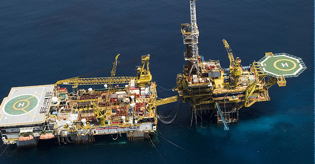
Tender assist drilling units (TADs) allow drilling operations to be carried out on a fixed platform without the need for a permanent drilling package on the platform. The TAD is stationed next to the platform and its drilling package is lifted onto the platform. The TAD remains in place in order to provide power and other services that support the drilling operation. There are two different types of TADs, a tender rig and semi-tender, both units carry the same equipment but the semi-tender is capable of operating in deeper waters and harsher environments

Rig Generations

7 basic generations determined by delivery year and water depth characteristics

Semi-submersible rig generations:

  • 1st Generation
    • Unit constructed from 1961 – 1972. Max water depth is N/A
  • 2nd Generation
    • Unit constructed from 1973 – 1979. Max water depth is N/A
  • 3rd Generation
    • Unit constructed from 1980 – 1985. Max water depth is N/A
  • 4th Generation
    • Unit constructed from 1986 – 1997. Max water depth is N/A
  • 5th Generation
    • Unit constructed from 1998 – 2004. Max water depth is N/A
  • 6th Generation   
    • Unit constructed from 2005 onwards. Max water depth is 10,000ft
  • 7th Generation
    • Unit constructed from 2015 onwards. Max water depth is 12,000ft

Drillship rig generations:

  • 1st Generation
    • Unit constructed from 1961 – 1970. Water depth is N/A
  • 2nd Generation
    • Unit constructed from 1971 – 1979. Water depth is N/A
  • 3rd Generation
    • Unit constructed from 1980 – 1985. Water depth is N/A
  • 4th Generation
    • Unit constructed from 1986 – 1997. Water depth is N/A
  • 5th Generation
    • Unit constructed from 1998 – 2005. Water depth is N/A
  • 6th Generation
    • Unit constructed from 2006 onwards. Max water depth is 10,000ft
  • 7th Generation
    • Unit constructed from 2010 onwards. Max water depth is 12,000ft

Jackup rig types

Four jackup type categories

  • High Specification
    • Water depth is 400ft+, with a hookload capacity of over 2,000kips
  • Premium
    • Water depth is 350ft+, with a hookload capacity from 0 – 1,999kips
  • Standard
    • Water depth is less than 350ft
  • Mat Cantilever/Slot
    • Any jackup that does not have an Independent Leg Cantilever (ILC) sub-type

Sub type definitions

  • Floating rigs
    • Midwater
    • Deepwater
    • Ultra-deepwater
  • Jackups
    • Independent Leg Cantilever
    • Independent Leg Slot
    • Mat Cantilever
    • Mat Slot
    • Cantilever

Floating rig water depths

  • Midwater
    • 4,000ft or less
  • Deepwater
    • 4,001- 7,499ft
  • Ultra-deepwater
    • 7,500ft and greater

Ref: http://www.infield.com/rigs/rig-glossary


Drilling Formulas Application Needs Your Feedback

$
0
0

In order to improve this application and fix some errors that we may not see, we need your help to send us your feedback about “Drilling Formulas Application”. You can give us any comments about this app (good, bad, need improvement) and we will try the best to do it even though app programming is not our expertise.

drilling-formula-need-feedback

Please feel free to send email to drillingformulas@gmail.com, leave comment on Facebook, Google+, or put some comments on this post.

Your help will be very useful for us.

In the future, we have plan to add several related drilling formulas in several topics as bit calculations, well control, snubbing, bullheading, etc. Please download this app into your Android mobile device so you will get an update automatically once we update this app.

Note: we don’t have the IOS version yet.


10 Tips to Make a Career in an Oilfield For New Personnel

$
0
0

Oil rig is basically a man made platform that is used for off-shore or land drilling. As an oil rig worker, one can work on both platforms, and is responsible for several tasks that are related to safely oil drilling. Usually the workers work for 14- 21 days at a stretch, prior to getting a shore relief. Apart from regular wages, the workers get all sort of facilities ranging from food, boarding and travel expenses. However, to get a job in oil rig as a rookie is quite difficult, because most of the oil rig managers seek for experience. Below we have mentioned some pointers that may come handy while trying to seek for a job in oil rig industry.

making-carreer-in-an-oilfield

Make sure that you meet all the basic requirements and are fully eligible for employment in oil rig.

Some of the key requirements are:

  • You must be over 18 years old
  • You must be physically and mentally fit. You must pass physical examination.
  • You must be a non-smoker and refrain from alcohol during 14- 21 days of duty.
  • You must be ready to take the odd schedule of oil rig worker. You must be prepared to work at night and for several days without any break in weekends.

Try to get some experience as a mechanic

Most of the oil rig workers have to deal with mechanical job. Hence, it would be better if you get some training as a cook, engineer, electrician, or medic.

Seek guidance from friends, relatives or acquaintances that are working in oil rig.

However, if you don’t know whom to ask, then this contact will come quite handy to you in getting all the valuable information about the industry. You can do an online research and go through the chat forums. With the help of chat forums, not only you will get valuable information, but you will also get to know whether there is some opening or job requirement in the oil rig sector.

Do a Proper Research before Applying in Oil Industry

You can go for an online course, community college course, or scroll through the library and get some books related to oil drilling, industry and its workers. Besides, you will also get to know the recent changes in rules and regulation of oil industry.

You must be able to convince your employers that you are truly interested in this sector and are eager enough to become a hardworking and valuable employee. If you do your home work properly and gain all the necessary basic information, you will not appear like a complete novice.

Look for job postings in newspapers or internet

Sites like Indeed, Monster and CareerBuilder are the best places online to find job postings. You can go through these postings and find out what oil rig companies are looking for in an oil worker, such as qualifications, experience, age criteria, etc. Usually you will come across oil rig titles such as Safety Man, Sub Sea Engineer, Derrick Man, Assistant Driller, Driller, Crane Operator, Storekeeper, Rig Welder, Rig Medic, Mudman, Tool Pusher, Mechanic, Electrician, Barge Engineer, etc. However, sometimes they need hard working labors in oil rigs that are called as “Roustabouts”.

You can search for job listings in local newspaper or through the contacts in oil industry. Find entry level positions that feature on-job training.

Prepare Cover Letter and Resume

Make sure to mention all the jobs you have done before that are relevant to oil rig. If you have worked as a labor, mechanic, or electrician, then make sure to highlight them.

  • A cover letter is usually a half to full page content that describes how your experience actually makes you a perfect candidate for this job.
  • Your resume must be about one to two pages long. Don’t forget to mention your qualification, achievements and quality in it. Your resume should be targeted for the job you are applying for, so it must be relevant enough.

Applying for the job

Make sure to apply at several places all at once; this will give you better chances of getting a call for interview.

Get BOSIET (Basic Offshore Safety Instruction & Emergency Training) Certification

This is mandatory for working in Denmark or Netherlands and UK. Besides you can even try to get certificate for Helicopter Underwater Escape Training.

  • You can get such training courses at marine safety schools or institutes. In fact, several seaside colleges in US and UK have marine safety schools.

Make sure to apply for TWIC (Transportation Worker Identification Credential), in case you want to work in US in Offshore Drilling.

You can simply visit twicprogram.tsa.dhs.gov and get the form. Fill up the form and visit TWIC enrollment facility to submit the form for application.

  • You will be asked to provide biographic personal information, photographs, fingerprints and identification documents. The TSA (Transportation Security Administration would then verify the information and later send the TWIC approval to enrollment center.

Additional Resources

Loss of Concentration While Breaking Out Connection

$
0
0

You need to watch this VDO. In just few seconds, the incident was occurred because the driller did not turn off a mud pump before breaking out the connection.

What Went Wrong?

– The driller did not pay attention to the operation.
– Stored energy of hydraulic pressure

How Can We Prevent This Situation?

– Raise awareness of people working on the rig
– Always check the pump status before starting any operation
– People working on the rig floor are required to check the pipe to see if the flow still continues
– Use a pneumatic mud bucket
– Watch out for each other

What Do You Think on How To Prevent This?


loss-of-Concentration-While-breaking-out-connection

Please feel free to give us any ideas.

Basic Understanding of Stripping Operation Well Control with Gas Influx

$
0
0

In the previous articles, we discuss about the stripping operation and techniques with non-migratable kicks as oil and water kick. This article will focus on the stripping operation with gas influx and we are going to describe some additional considerations that you need to account for. Gas kick is different from the liquid kicks because gas can naturally migrate. The gas migration affects the stripping operation because increase in casing pressure due to gas migration must be taken into considerations.

basic-understanding-of-stripping-operation-with-gas-kick

Gas migration can increase both surface and bottom hole pressure. If pressure increased by gas migration is not handled properly, the well can be fractured and it results in bad complications while performing well control operation.

Figure 1 - Gas Migration Increase Wellbore Pressure

Figure 1 - Gas Migration Increases Wellbore Pressure

We will need to apply volumetric well control into the stripping operation so the procedure is called “Stripping with Volumetric Control”. This procedure will account for both pressure increased by gas migration and pipe displacement.

There are 3 figures that you need to determine before starting the operation;

Safety Factor – It is the small overbalance pressure to prevent you to be accidentally in underbalanced condition.

Pressure Increment – It is a pressure change for each step for bleeding off.

Mud Increment – It is the mud volume equivalent to Pressure Increment.

We will go through into detailed of the stripping with volumetric control procedure in a next topic.

The critical part of this operation is when the drillstring penetrates into the gas kick because height of gas increased because the annular profile changes. The will result in reduction of hydrostatic pressure. The adjustment must be made in order to compensate for loss of hydrostatic pressure. Additionally, when the drillstring penetrates into the gas kick, a new mud increment, which is based on the calculation of annular volume between ID of casing or wellbore and OD of drillstring, must be used.

With gas in the wellbore, it is quite complicated for time estimation when the drill string will penetrate the gas kick because of gas migration. You must do two calculations in order to accurately estimate the time when the drill string will penetrate the gas kick.

The first step – This is to determine gas migration rate.

Gas migration rate (ft/hr) = ∆SICP ÷ (0.052 x MW x ∆T)

Where;

∆SICP = change in casing pressure, psi

MW = mud weight in hole, ppg

∆T = Time interval of casing pressure change, hr

The second step – The time can be calculated by using the following relationship:

T = (Dgas– Dbit) ÷ (GMR + SS)

Where;

T =Time to penetrate the gas kick, hrs

Dgas = Gas kick depth, ft

Dbit = Bit depth, ft

GMR = Gas migration rate, ft/hr

SS = Stripping speed, ft/fr

Warning - This calculation may not be accurate because the calculation above is based on the known location of gas kick and the gas bubble is all together in one gas kick. If the gas is swabbed, the location of gas kick is possibly at the bottom of the bit.  Gas migration rate may change due to wellbore temperature vs depth. For the practical stand point, you may need to add safety factor which will compensate the decrease in hydrostatic and you use the conservative fluid increment by using the capacity factor around the drillstring.

Please see the following example for the calculation.

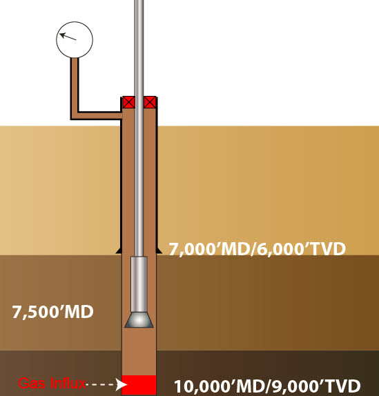
Determine gas migration rate and time to penetrate the gas kick based on the following information.

  • Shoe depth = 7,000’MD/6,000’TVD
  • Hole depth = 10,000’MD/9,000’TVD
  • MW = 12.0 ppg
  • Bit depth = 7,500 ft
  • 5” DP, 19.5 ppf
  • 5” DC = 800 ft as BHA
  • Pit gain = 35 bbl
  • Hole size = 8.5 inch
  • Casing ID = 8.835 inch
  • SICP = SIDP = 250 psi
  • Surface pressure increases to 500 psi in 30 minutes due to gas migration.
  • Average stripping speed = 200 ft/hr

Figure 3 – Well Diagram for This Example

Figure 3 – Well Diagram for This Example

Solution

Determine gas migration rate (ft/hr)

Gas migration rate (ft/hr) = ∆SICP ÷ (0.052 x MW x ∆T)

Gas migration rate (ft/hr) = (500 – 250) ÷ (0.052 x 12 x 0.5)

Gas migration rate (ft/hr) = 801 ft/hr

Determine length of 35 bbl gas kick in 8.5” hole and top of gas kick

Length (ft) = Kick volume (bbl) ÷ Hole capacity (bbl/ft)

Hole capacity (bbl/ft) = 8.52 ÷ 1029.4 = 0.0702 bbl/ft

Length (ft) = 35 ÷ 0.0702 = 499 ft

It means that top of kick is about 499 ft from the bottom.

Top of gas kick = 10,000 – 499 = 9,501 ft

Determine time to penetrate kick

T = (Dgas– Dbit) ÷ (GMR + SS)

T = (9,501– 7,500) ÷ (801 + 200)

T = 2 hrs

Based on the given information, it will take a total of 2 hours to penetrate the gas kick.

Reference books: Well Control Books

The Fastest Running Casing Speed on The Planet!!!

$
0
0

Running casing is one of the most critical parts of drilling operation therefore people want a safe and efficient running casing operation. Without proper safeguard in place, the casing run can be fast like this but it was not a successful job.

From this VDO, it seems like the surface casing was run into the well but there was something wrong on the rig floor that resulted in dropping casing into the wellbore. We share this vdo because we would like to promote safe work place and let us learn from it.

What Do We Learn from This Footage?


fastest-casign-running2
There was something wrong on the rig floor. Some handling tool might fail to hold the casing string. Crew may unintentionally release slip. Many more things were happened that we don’t know. However, we would like to take an opportunity to discuss how to prevent this situation.

• Review a job procedure with all related personnel
• Review crew positions while working prior to commencing the job
• Encourage crew to stop the job any time
• Emphasize that FAST is not the ultimate goal for the operation. Safe and efficient operation is the main key.
• Inspect all casing handling gears as elevators, slips, dog collars, etc
• Discuss potential hazard for the operation and have open-ended questions asked the crew to ensure that they know their roles and responsibilities

What is Your Thought about This?


Please feel free to share with us.

Oilfield Acronym Spreadsheet

$
0
0

You may get confused when you see a lot of oilfield acronym used for oil and gas industry so we would like to make your life easier by collecting oilfield abbreviations in both Microsoft Excel and PDF files. There are a total of 2,428 acronyms related in oil and gas industry.

oilfield-acronym

The image below is the capture screen of the PDF version.

Figure 1 - Oilfield Acronym PDF

The Excel file version looks like this.

Figure 2 - Excel file version of oilfield acronym

Download the oilfield acronym from the download links below;

PDF version

Oilfield Acronym (PDF)

Excel version

Oilfield Acronym (Excel)

We would like to keep update this file so if you have any oilfield abbreviations that we don’t have, please feel free to give us the comment in the comment box below. We wish you like our stuff.


GOM Offshore Oil Platform Rig Explosion – Alfa Platform Pemex Oil – 300 Evacuated

$
0
0

Safety is Always !!!

It was a very sad oilfield incident and these are NEWS from two sources, AP and reuter.

MEXICO CITY (AP) — A fire erupted Wednesday at an oil platform in the Gulf of Mexico, killing four workers, injuring 16 and forcing the evacuation of 300, Mexico’s state-owned oil company said.

A survivor of the blaze on the Abkatun Permanente platform in the Campeche Sound said workers “jumped into the sea out of desperation and panic.”

“There was nothing you could do but run,” said Roger Arias Sanchez, an employee of Petroleos Mexicanos’ contractor Cotemar who escaped the burning platform in an evacuation boat. He spoke in Ciudad del Carmen in Campeche state, where most of the injured and evacuated workers were taken.

GOM Offshore Oil Platform Rig Explosion - Alfa Platform Pemex Oil  - 300 Evacuated1

Eight firefighting boats were trying to extinguish the fire, said Pemex. Mexico’s Energy Security Agency said the fire “is being extinguished.”

On its Twitter account Wednesday afternoon, Pemex raised the death toll from one to four. In an earlier statement, it said that two of the 16 injured workers were in serious condition. Many appeared to be Cotemar employees.

Pemex’s media office said it was unclear whether any significant amount of oil had spilled from the shallow-water Abkatun Permanente platform, which largely serves to separate gas, oil and other petroleum products, and pump them to refineries onshore.

The platform lies off the coast of the states of Campeche and Tabasco. It is further out to sea than the platform involved in the last severe fire in the area, the 2007 fire at the Kab 121 offshore rig.

That accident was caused by high waves that hit the rig, sending a boom crashing into an oil platform’s valve assembly. The accident killed at least 21 workers and the rig spilled crude and natural gas for almost two months.

Mexico’s worst major spill in the Gulf was in June 1979, when an offshore drilling rig in Mexican waters — the Ixtoc I — blew up, releasing 140 million gallons of oil.

It took Pemex and a series of U.S. contractors nearly nine months to cap the well, and a great deal of the oil contaminated Mexican and U.S. waters.

Update ( Reuters ) : 4 Died , 302 Evacuated , 45 injured

Fire Engulfs Pemex Oil Platform 300 Evacuated

GOM Offshore Oil Platform Rig Explosion - Alfa Platform Pemex Oil  - 300 Evacuated3

Mexican state-run oil company Pemex said at least one person died and 16 were injured after a fire broke out on an oil platform in the Gulf of Mexico, sparking the evacuation of around 300 workers.

Local emergency services reported that as many as 45 people were injured at the blaze that erupted overnight on the Abkatun Permanente platform in the oil-rich Bay of Campeche.

Pemex said it was battling the flames with eight firefighting boats, and that a contractor for Mexican oil services company Cotemar had died in the blaze. One of the injured was in serious condition, the company added.

Earlier, a spokesman for emergency services in the nearby city of Ciudad del Carmen said authorities had registered 45 people with injuries due to the fire.

GOM Offshore Oil Platform Rig Explosion - Alfa Platform Pemex Oil  - 300 Evacuated2

The platform forms part of the Abkatun-Pol-Chuc offshore complex. According to data from the U.S. Energy Information Administration, production at the complex has fallen steadily since the 1990s to below 300,000 barrels per day (bpd) in 2013.

Mexico currently produces just under 2.3 million bpd.

It was not immediately clear what had caused the fire in the Gulf, which is home to Mexico’s biggest oil field.

Cotemar is based in Ciudad del Carmen and provides offshore services to Pemex including platform refurbishment, maintenance, and maritime transport, according to its website.

Pemex has suffered a number of accidents in recent years, with at least 37 people killed by a blast at the company’s Mexico City headquarters in 2013. Another 26 people were killed at a fire in a Pemex natural gas facility in September 2012.


Stripping Procedure without Volumetric Control for Non-Migrating Influx

$
0
0

This article will teach you about the stripping procedure for non-migrating kick. This procedure is used to strip to desired depth but it won’t account for volumetric bleed therefore it is mainly applicable for stripping with non-migrating kicks as water or oil.

 37-Stripping-procedure-without-volumetric-control

The stripping procedures are as follows;

Figure 1 - Stripping to the bottom with non-migrating kick

Figure 1 – Stripping to the bottom with non-migrating kick

1. Calculations

  • Determine whether the drillstring weight is over the pressure force pushing upwards.
  • Determine how many feet that you need to strip to penetrate the kick
  • Determine pressure increase when the drillstring penetrate the kick. You can read more details about this topic here –xxxxx
  • Determine safety factor. If you plan to use the constant surface pressure method for the stripping operation, the safety factor added into the system must be sufficient to compensate the effect of influx penetration.
  • Determine volume bleed back per stand if you plan to use the volume accounting method.

2. Stab a safety valve (full opening safety valve) and follow by an IBOP valve.

Figure 2 - Stab a safety valve and IBOP

Figure 2 - Stab a safety valve and IBOP

3. Ensure no leakage between connections.

4. Adjust the closing pressure to allow the stripping operation.

5. Strip the drillstring into the well until you get the desired safety factor. While stripping, small volume of fluid leakage around the pipe is a good sign because the closing pressure is not too much but the leak must stop when the stripping operation is stopped.

Figure 3 - Stripping with adjusted closing pressure

Figure 3 – Stripping with adjusted closing pressure

6. Strip to the required depth based on your selected method. You have a choice to use either the volume accounting or the constant surface pressure. You can read more details about these two methods from this article “Stripping Methods for Non Migration Kicks When There is an Off Bottom Well Control”.

Reference books: Well Control Books


Open Hole Fishing VDO Training

$
0
0

Open hole fishing is one of the most critical operations in drilling. It involves a lot of expertise and experience of the personnel. This VDO by Weatherford Fishing Services demonstrates you about the open hole fishing. This is highly recommended for you to watch it. Additionally, the full VDO transcript is provided.


Full VDO Transcript – Open Hole Fishing VDO Training

weatherford fishing

Openhole fishing involves the removal of unwanted objects from the wheel bore. The objects can be tools, equipment and broken pieces of drill pipe, bits or tubulins. Openhole fishing begins following a Backoff in the drill string at or above the stock point of the fish in the wellbore leaving an accessible fish top.

The fish can be removed using special tools and techniques. A Scew-in sub is one of the most common fishing tools. Its modified pin can be used to catch an undamaged fish. The overshot tool because of its versatility is frequently used in fish recoveries. Its simple design includes a circulating and releasing action as well as a 360 degree catch of the fish. Normally the overshot or screw-in sub is connected to the bottom of the bumper sub and fishing jars on the fishing assembly. As the tool is lowered over the fish the top of the fish passes through the tool into the bowl. When the assembly is raised grapples engage the fish at a lower point and it is work free and pulled upward.

If the top of the fish is bent, twisted or broken it should be dressed off to provide a clean top so the grapple can secure it firmly. Dressing off is achieved with a Skirted or hollow fluted mill. Several types of mills are available for this purpose and other jobs.

In a washed out hole use of a hydraulic Knuckle joint located above the overshot kicks out under pump pressure to increase the sweep of the overshot to facilitate capture of an allusive fish. When the severe wash out, a Wall hook guide run on the bottom of the overshot further improves the search and capture of the fish.

When the fish cannot be dislodged by pulling with the overshot a jarring assembly run in the fishing string can be activated to strike heavy blows either up or down on a stuck fish to free it. The down action is achieved with a Bumper jar; essentially a slip joint with a sliding stroke. The impact enhanced by the weight of drill collars above the Bumper jar results in a sharp blow with the fishing string. Dropping the string quickly produces a sharp downward blow on the fish. This jarring action is especially effective in freeing PC Pipe or a string that is stuck as a result of an upward pull.

In many cases a stuck fish will require a powerful upward jar to free it. Hydraulic fishing jars permit an upward impact. The impact produced by a Hydraulic jar depends on the amount of pull taken on the tool before it trips. As indicated earlier the impact of a Hydraulic jar is enhanced by the weight of Drill collars placed above the tool. A jar accelerator further intensifies the effect of a jar at any depth. It is especially effective in shaft fishing operations where elasticity present in longer drill strings is not available. The use of an accelerator also keeps the energy of the jar impact form being lost a mole.

When a fish is stuck and cannot be jarred or worked free a widely used practice called Washover is employed. The Washover operation is the most successful way to free a fish and requires expert judgment in both pipe selection and in its proper running application. As mud and hole conditions are critical in many cases a bit drip may be necessarily to condition the hole prior to running the Washpipe.

Essentially Washover operation involve a pipe string that slips over the stuck fish allowing fluid to circulate in the annalist between the fish and the inner wall of the Washover pipe. Fluid under pressure flushes out debris cut lose by the rotary shoe run on the bottom of the Washover pipe. The washed over fish secured by an overshot or a screw-in sub and then be backed and removed to the surface.

The Washover pipe selected requires and inside diameter large enough to accommodate the fish and an outside diameter that can rotate without sticking in the open hole and still allow circulation.

Various types of Weatherford shoes are available. Each shoe is custom designed for a particular procedure. Tooth-type shoes for example are recommended when the formation to be cut is relatively soft. When metal such as tool joint or stabilizer blades must be cut the rotary shoe is dressed with Tungsten carbide or diamonds internally, externally or both; tailored specifically for the task. Proper rotary shoe selection requires expertise. An improper choice could severely damage the fish complicating the recovery operation. Occasionally the drill pipe maybe plugged, usually by mud. Cutting the freed drill pipe with a mechanical outside cutter run on the Washpipe would remove the obstruction and establish a clean workable top. Following Washover the Washpipe is pulled up and the shoe removed and replaced by a mechanical Outside cutter. Run into the well and over the freed fish the cutter is engaged. With a slight upward strain cutter knives are fed through the wall of the drill pipe fish and the fish is parted. Rotation is then stopped and the cut piece of fish is recovered and pulled to the surface.

When the fish is stuck off bottom a Washpipe spear may be run in conjunction with the Washpipe and screwed into the fish prior to the Washover procedure. This prevents a fish freed by the Washover operation from dropping to the well bottom and damaging the wellbore, drilling string or drilling bit.

Openhole fishing also involves the retrieval of Junk at the well bottom. Junk is defined as any unwanted material in the hole that hampers operations; such as, accidentally dropped tools, metal debris, parts of equipment including cones from drill bits. A commonly used retrieval tool is the Fishing magnet. Fishing magnets are especially cost effective for retrieving smaller fairish objects such as bit cones, slips and mill cuttings.

Permanent magnets have circulating ports around the outer edge so that fill and cuttings can be washed away exposing the Junk for proper magnetic contact. Magnets are furnished with flush guides, lift guides or mill guides which help in washing and securing the Junk. The magnet is lowered to the well bottom while circulating and then pulled to the surface. This activity may be repeated until the wellbore is cleared of all Junk.

Where Junk pieces cannot be caught by a magnet or consistent not fairish metals Weatherford employs specialized Junk baskets depending on the type of formation encountered. These retrieval tools consist of three basic types.

The simplest to use is called a Boot basket. It is run directly above a Junk mill or a rock bit that cuts the Junk into small pieces. Fluid circulation deposits these pieces into the basket which is raised to the surface.

In soft medium formations a coin tied basket commonly known as a Globe basket can be run to cut a short core in the bottom of the well. This core as well as any Junk contained in it is held in place by Retaining fingers and removed to the surface.

In hard formations a jet powered or Reverse circulating basket is a highly effective tool. Lowered to the bottom it rotates slowly with circulation to flushing settlings from the Junk. A ball is dropped into the drill pipe and pumped down until the ball seeps in the retriever. The flow of the fluid is diverted to the outside the tool which causes two things to occur. It establishes reverse circulation and a venturi effect which then creates a partial vacuum inside the Junk basket. These two forces propel the Junk into the basket. Captured Junk is secured by the hinged Retaining fingers. This action continues until all Junk is removed from the hole.

Stripping Procedure with Volumetric Control For Migrating Kick

$
0
0

With gas kick in the well, the conventional stripping method is not application because it won’t account for the gas migration and expansion; therefore, the special stripping procedure, Stripping with Volumetric Control, will be utilized for this case. This procedure is designed to strip the drill string back into the well with gas influx while the bottom hold pressure is maintained nearly constant.

Figure 1 - Stripping With Volumetric Control

 Figure 1 - Stripping With Volumetric Control


The Stripping with Volumetric Control procedures are as follows;

38 Stripping procedure with volumetric control

1. Calculations

  • Determine whether the drillstring weight is over the pressure force pushing upwards
  • Select required Pressure Increment (PI)
  • Select Safety Factor (SF)
  • Determine Mud Increment (MI)

Mud Increment (MI) is calculated by the following equation

MI equation

Where;

MI = Mud Increment (MI), bbl

PI = Pressure Increment (PI), psi

ACF = annular capacity factor, bbl/ft

MW = mud weight, ppg

  • Determine how many feet that you need to strip to penetrate the kick. This calculation must be account for gas migration and stripping speed. You can read more details here -
  • Determine pressure increase when the drillstring penetrate the kick. You can read more details about this topic here –Kick Penetration For Stripping Operation

2. Stab a safety valve (full opening safety valve) and follow by an IBOP valve.

Figure 2 - Stab a safety valve and IBOP

Figure 2 – Stab a safety valve and IBOP

3. Ensure no leakage between connections.

4. Adjust the closing pressure to allow the stripping operation.

5. Strip the drillstring into the well until the casing pressure increase by Safety Factor (SF) + Pressure Increment (PI). No bleeding off during the step#4.

6. Maintain constant casing pressure by bleeding off fluid while stripping until the difference between the drillstring displacement and the actual mud bled back equals to Mud Increment (MI).

7. Strip into the well without bleed off fluid until the casing pressure increases by Pressure Increment (PI).

8. Repeat step#6 and #7 until the drillstring penetrates the gas kick. Once the gas kick is penetrated, you need to allow casing pressure increased by pre-determined figure. This is will be your new casing pressure. Practically, you can add the pressure increase caused by the kick penetration into the safety factor and use the mud increment based on the volume between drillstring and the casing. This will be the conservative way which can prevent you to be in an underbalanced condition.

9. Strip into the desired depth by repeating step#6 and #7.

Reference books: Well Control Books

5 Useful Oilfield Resume Templates

$
0
0

Your oilfield resume is one of the most important parts to get interviewed for oil and gas jobs. With current oil price, it is even harder to get hired into this industry and a lot of people are looking for new positions because of this slow down trend. However, there are still plenty of positions in oilfield but you need be outstanding from groups of people.

free resume template

How Can I Do That?

You need to write a professional resume definitely and you can find how to write excellent oilfield resume from here –


Template 1

Template 1

Template 2

Template 2

Template 3

Template 3

Template 4

Template 4

Template 5

Template 5

Download links are below;

Template 1: http://bit.ly/1IpoNSN

Template 2: http://bit.ly/1bcVEzM

Template 3: http://bit.ly/1CZ0sOI

Template 4: http://bit.ly/1OTsF27

Template 5: http://bit.ly/1O3dXsp

Not only do you have professional look resume, you must also properly format your CV to catch your potential employee eyes. You may ask how to get the right layout for your oilfield CV. Our simple answer is to use resume templates.

We would like to share 5 professional oilfield resume templates which you can freely modify to match with your experience. These CV templates are simple styles which look very professional for job application.

Additional Resources

Water Well Drilling – Old School

$
0
0

I am not sure which country. This is how they actually drill a water well with very old school method.

Basically from what I’ve seen from the footage, it has the set up which is similar to a drilling rig. There is a circulating hose connected at the top. One man rotates the tubular and this represents a rotating system on the rig as a rotary table or top drive. Since there is no weight (I guess), one man stand on top of the tubular while being rotated in order to apply weight down hole in order to make a hole. The return is back from the annulus to surface and this is similar to mud circulating system.

30 old school water well drilling

This is very interesting to learn how people use their tool to drill a water well. I think they don’t know how to drill like us but they know how the basic system should be.

Any comments?

Perforating For Inflow Performance In Natural Completions – SPE Distinguished Lecturer Program

$
0
0

This is the distinguished lecturer program supported by SPE in the topic of “Perforating For Inflow Performance In Natural Completions” By Mark S Brinsden. This presentation is very interesting  about inflow performace of the well and perforation.

What will you learn from this presentation?

  • Introduction
  • The Traditional Approach To Perforating
  • Measuring Perforator Performance
  • Modeling Perforators For Well Performance
  • Case History
  • Recent Advances In Perforating Technology
  • Implementing What We Have Learned

These images are samples of presentation.

PERFORATING FOR INFLOW PERFORMANCE 1

PERFORATING FOR INFLOW PERFORMANCE 2 PERFORATING FOR INFLOW PERFORMANCE 3 PERFORATING FOR INFLOW PERFORMANCE 4 PERFORATING FOR INFLOW PERFORMANCE 5 PERFORATING FOR INFLOW PERFORMANCE 6

Download the presentation here –

http://bit.ly/1HtmJMn

Ref site: http://www.perforators.org/

Two New Efficient Oil Drilling Techniques

$
0
0

Two new efficient oil drilling techniques

The U.S. increased oil reserves can be attributed to the development of revolutionary technology that has enabled them to extract oil from the ground.

Thanks to the efforts of Texas Tech University, miners have improved their methods of drilling and extracting oil in the form of “Zipper Fracking.” This method is similar to the more common hydraulic fracking but instead of drilling one well, miners drill two wells side by side. After both wells have been drilled, they are then fracked at the same time.

The second drilling technique that miners have begun to use is called “Stacked Laterals.” It is most useful in offshore drilling since building platforms just to extract oil from shale out in the ocean isn’t that cost-effective. So whenever operators are out in the water, they now drill several wells from a single pad (ergo, stacked laterals). This saves time but and money, with the stacked laterals increasing oil production by around 200%.

From June 2011 to June 2014, several major shale regions in the U.S. that used the new drilling methods have enjoyed an increased amount of yields. In Eagle Ford Texas, production per drilling rig increased from 198 barrels a day in 2011 from 476 barrels in 2014. In Bakken, oil production increased from 213 barrels a day to 505.

New drilling techniques make oil extraction easier and it will be more economical with the discovery of new technology. Sulzer, Unaoil’s partner in servicing oil and gas companies in North Rumalia, has developed a new generation hydro-powered water drill which is both cost-effective and environmental friendly because it uses water instead of oil for lubrication. It is now being used by some firms and could potentially be a game-changer in the future of oil drilling.

Currently, there’s no end in sight for the U.S.’ production of oil. Experts predict that it will continue to soar as private companies are continuously finding ways to extract more oil from shale.


Practical Considerations for Stripping Well Control Operation

$
0
0

This section will discuss some practical stand points of the stripping operation with and without volumetric control. Additionally, this will summarize some key points for both methods of stripping for off bottom well control.

practical consideration

General Practical Considerations

Stripping operation requires accurate measurement of fluid bled off therefore it is very critical to have a small trip tank or a stripping tank for the operation. Furthermore, when the drillstring is stripped deeper, you might need to fill the pipe. You need to ensure that the volume filled up will not create any confusion with the bleed of volume. There are some cases when personnel don’t track the volume properly and finally the kick is unintentionally introduced into the wellbore.

Once you identify that you need to strip to the bottom, the stripping operation should be conducted as soon as possible. Gas kick at the deeper depth of the well will have a little expansion therefore you can minimize the expansion effect. In some cases, the drillstring can be successfully stripped back to the bottom before the first mud increment is reached. This will minimize the complication caused by the gas expansion.

Stripping Without Volumetric Control

Stripping to bottom using Non Volumetric Control is applicable for non-migrating influx such as oil and water kick and it has less complexity than the stripping with volumetric control. Since the kick does not migrate, there will be no increase in surface pressure and the concept of stripping is to control bottom hole pressure while a drillstring is stripped into a shut-in well. There are two methods that you can use as follows;

  1. Volume accounting method – the concept of this method is to bleed of the fluid at the same volume as the drillstring displacement stripped into the well.
  2. Constant casing pressure method – the concept of the method is to maintain casing pressure constant during the stripping operation but it requires pressure compensation when the drillstring penetrate the influx. Therefore, it is recommended that you add the safety factor that must be more than the pressure increase due to the kick penetration in order to control the bottom hole pressure. If the safety factor is added into the system properly at the beginning of the operation, the well will still be in an overbalanced condition after the string penetrates into the kick.

Stripping With Volumetric Control

Stripping with volumetric control is more complex than the first method because it deals with gas migration. What’s more, there are several small things that you need to consider such as changing in mud increment when the string penetrates the gas bubble, time to penetrate kick, etc. There are also several unknown values associated with the calculation so it makes the operation quite difficult.

In order to be more practical with this stripping method, you need to get rid of the time to penetrate to the bubble and there are two practical ways to do.

Safety Factor The first way is to add the pressure increase due to kick penetration into the safety factor at the early step of the operation. The safety factor will prevent the additional kick when the gas kick in penetrated. You can estimate the required safety factor here –

Conservative mud increment – Mud Increment (MI) (MI) is calculated by the following equation

MI equation

Where;

MI = Mud Increment (MI), bbl

PI = Pressure Increment (PI), psi

ACF = annular capacity factor, bbl/ft

Before you penetrate the kick (the influx is below the bit), ACF is calculated based on hole capacity but once the drillstring penetrates the kick, the ACF is  calculate based on the capacity between around the drillstring.

In order to make the MI more practical, it is recommended to determine the MI based on the ACF around the drillstring and use this one figure for entire operation. The MI will be less than the one that is calculated when the gas kick is below the bit therefore the wellbore will be slightly overbalanced.

Reference books: Well Control Books


Down Hole Video Camera – Amazing To See How Actual Oil & Gas Wells Look Like

$
0
0

Have you ever imagined about the down hole conditions of oil and gas wells? 

downhole-vdo-camera

We initially think that they might look pretty smooth tubular with perforated holes and down hole tools. Until we’ve seen these footage, you will be amazed how the technology can help you to look into down hole. They are excellent VDOs because they demonstrate the well conditions in various situations. You can see down hole tools (packer, side pocket mandrel, etc), perforated holes, damaged casing, hole shape, tubular conditions, etc. What’s more, down hole camera can demonstrate how oil and gas wells produce. With this application, it will help oil companies to identify the well production issue more accurately.

Please feel free to share your comments :)

Stripping with Volumetric Control Steps and Example Calculations

$
0
0

This example demonstrates the calculations and the steps of the stripping with volumetric control so it will help you understand about what calculations required are and how to perform the stripping with volumetric control.

stripping with volumetric well control

Gas kick at the bottom but the drillstring is out of bottom. The kick is introduced while pulling out of hole and the following information below is the well information.

  • Pit gain = 30 bbl
  • Shut in Drill Pipe Pressure = 400 psi
  • Shut in Casing Pressure = 400 psi
  • Current mud weight = 11.0 ppg
  • Casing shoe depth = 6,000’MD/6,000’TVD
  • Hole TD = 9,000’MD/9,000’TVD
  • Hole size = 12.25”
  • Casing ID = 12.5”
  • Drill pipe size = 5”, 19 ppf
  • BHA consists of 6.5” drill collar
  • Length of BHA = 800 ft
  • Average pipe per stand = 94 ft
  • Rate of increase in casing pressure = 150 psi in 1 hour
  • Assume gas density = 2 ppg ( 0.104 psi/ft)

Figure 1 – Well Diagram

The decision is made to strip to the bottom. Safety Factor and Pressure Increment are 100 psi.

Assumption: Gas kick at the bottom

Kick Height

Kick height = kick volume ÷ hole capacity

Hole capacity = 12.252 ÷ 1029.4 = 0.1458 bbl/ft

Kick height = 30 ÷ 0.1458 = 206 ft

The top of gas kick is at 8,974 ft (9,000 – 206) before it migrates.

Figure 2 – Top of Kick


Gas Migration Rate

Gas migration rate, fph = (Rate of increase in casing pressure, psi/hr) ÷ (0.052 x MW)

Gas migration rate, fph= 150 ÷ (0.052 x 11.0)

Gas migration rate = 262 fph

Figure 3 – Gas Migration

Mud Increment

Mud Increment (MI) is calculated by the following equation

Where;

MI = Mud Increment (MI), bbl

PI = Pressure Increment (PI), psi

ACF = annular capacity factor between casing and drillstring, bbl/ft

MW = mud weight, ppg

ACF = (12.52 – 52) ÷ 1029.4 = 0.1275 bbl/ft

Mud Increment (MI) = 22.3 bbl

Metal Displacement per Stand

Metal Displacement (bbl) = (OD2 x Average Length) ÷ 1029.4

Metal Displacement (bbl) = (52 x 94) ÷ 1029.4

Metal Displacement (bbl) = 2.3 bbl

Stripping with Volumetric Control Procedures

  1. We determine the Safety Factor (SF), Pressure Increment (PI) and Mud Increment (MI) as per the calculated shown in the above section
  2. Strip into the well until the casing pressure increase is equal to Safety Factor (SF) + Pressure Increment (PI) which is 200 psi. At this stage, the overbalance is 200 psi (100 + 100) and there is no bleeding back volume. From this example, we strip 2 stands to reach this point.

Figure 4 – Strip to get SF + MI

Figure 5 – Strip to get SF + MI Diagram

  1. Hold casing pressure constant and bleed off fluid volume while stripping in hole. For this step, we need track the actual volume bled back which is equal to volume bled off minus pipe displacement.


Figure 6 – Bleed off volume while stripping

Let’s take a look at Figure 6, the stand#3 bleeds 2 bbl and the metal displacement is 2.3 bbl. Therefore, you will have only 1.7 bbl of mud bled off. The overbalance reduces to 192 psi because 1.7 bbl of mud is out of the wellbore. You need to strip in until the total bled minus total stripped is equal to 22 a target mud increment which is 22.3 bbl.

Figure 7 – Bleed off while stripping until the mud increment is reached.

According to Figure 7, you need to strip a total of 12 stands in order to reach the target MI at 22.3 bbl and this point will have only 100 pis over balance.

Figure 8 – Stripping until the MI is reached.

  1. Strip in a shut in well until the safety factor is reach. At this example, we strip in to get additional 100 psi so the casing pressure will be 700 psi and the overbalance is 200 psi.

Figure 9 – Stand#13 stripped in a shut in well

Figure 10 – Strip in a shut in well until 100 psi is reached (700 psi surface pressure)

  1. We will continue step#3 and step#4 until the drillstring reaches the bottom or the desired depth. Then you can carry on the conventional well control methods as driller’s method, wait and weight etc.

Figure 11 – Continue Stripping by repeating step#3 and step#4


Figure 12 – Strip to desired depth

Reference books: Well Control Books


Directional Drilling Disaster ?

$
0
0

Have you ever seen this VDO?

In the VDO, it stated that this was a false calculation which was result this directional drilling disaster. However, when we see this footage, we don’t really believe that this situation was happened for oil and gas drilling. 

directional disaster myth

Why Do We Think Like This?

Firstly, from the technical perspective, it is very difficult to drill almost 180 degree from a vertical line (0 degree inclination). There are no oil and gas directional drilling tools as far as we know which can do this task. Secondly, it is very hard to believe that the directional drilling team do the wrong calculation because inclination changes are so obvious.

What Is This?

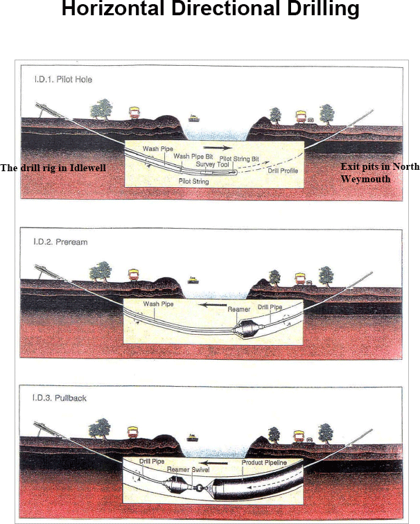
You may ask us what this vdo is if it is not oil and gas drilling. We try to find information from the internet and we’ve found that “Horizontal Directional Drilling” is the drilling technique of installing underground pipes, conduits and cables in a shallow arc along a prescribed bore path by using a surface-launched drilling rig, with minimal impact on the surrounding area.

What Do You Think About This?

Please feel free to leave any comments here.

Accident of Jack Up Rig Offshore Mexico – Results In 2 Fatality, At Least 10 Injured

$
0
0

May 5 (Reuters) – Mexican oil company Pemex said an accident on Tuesday has left an offshore maintenance rig in the southern Bay of Campeche listing, killing two workers, but has not affected crude production.

Accident of Jack Up Rig Offshore Mexico 1

Pemex said the Troll Solution rig, which was contracted to operate in Pemex’s Abkatun-Pol-Chuc shallow water oil field, was positioning itself to carry out maintenance on wells linked to the Caan Alf platform.

It earlier reported that two workers had suffered minor injuries.

“The accident on the Troll Solution platform does not affect production because it is a mobile platform dedicated to well maintenance,” Pemex said in a Tweet.

Oilfield services firm Typhoon Offshore, owned by Mexican conglomerate Grupo Salinas and operator of the platform, said in a statement that the platform had been completely evacuated and that 10 workers were injured and receiving medical care.

Local media put the injured toll at 28 workers.

A Grupo Salinas spokesperson added that there was no oil or gas spilled as a nearby well was closed prior to the incident.

Photos circulated on social media showed dark streaks in the water stretching a few hundred meters (yards) from what appeared to be the platform, which was tilting steeply.

A Pemex spokesman also said there had been no crude spill but added that the platform probably contained diesel. “That could have fallen into the water,” he added.

The Caan field where the accident occurred produced nearly 12,000 barrels per day (bpd) of crude in March, according to Pemex data. That in turn is part of the Abkatun-Pol-Chuc area, which produced almost 309,000 bpd in March.

Pemex said the platform was continuing to lean into the sea, but another spokesman for the company added that the accident had not “compromised” any wells.

The incident was the second platform mishap in barely a month to hit the Mexican oil giant, which made a loss of more than $6 billion in the first quarter of 2015.

On April 1, at least four people died at a fire in a separate platform in the Abkatun Pol Chuc complex, which temporarily dented production in the area.

Accident of Jack Up Rig Offshore Mexico 2

Around 70 percent of Pemex’s crude oil output comes from the southern Gulf of Mexico.

Pemex said around 100 workers were evacuated.

Ref: http://www.reuters.com/article/2015/05/05/mexico-oil-accident-pemex-idUSL1N0XW1SS20150505


Viewing all 497 articles
Browse latest View live


<script src="https://jsc.adskeeper.com/r/s/rssing.com.1596347.js" async> </script>